Creating Open World Environments in Unreal Engine 5: Part 2 - Asset Creation
Recent Escape Studios graduate Rodolfo Silva explores environment art creation, emphasising asset creation including modeling, texturing and optimisation.
Recent Escape Studios graduate Rodolfo Silva explores environment art creation, emphasising asset creation including modeling, texturing and optimisation.

Recent Escape Studios graduate and Maxon ZBrush expert, Rodolfo Silva, has created a three-part series covering the complexities of 3D Environment Technical Art.
In his first article, he delved deep into the pre production and setup of the technical aspects of the landscape system in Unreal Engine 5. In this article, Rodolfo shows you how he created all the models and textures for the assets in the environment, including the foliage assets while still planning ahead for optimisation and for further technical art systems to be implemented.
The blockout stage in the environment creation process was done after completing the final design of the landscape, all technical research had been performed and after the utilisation of Gaea within the workflow had been established. After the creation of the final terrain ‘Height map’, I imported it into Unreal Engine, where the blockout phase would begin.
The blockout stage itself consisted of:
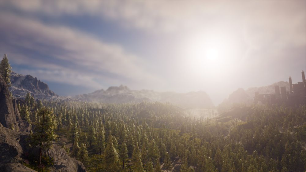
The materials were made to test the landscape blending using ‘RVT’ and the procedural aspect of snow cliffs, but they also served as a guide for determining the ideal location to place the forest area and castle buildings (Figure 1).

The initial design of the forest area consisted of a region of the map characterised by a substantial slope and a river that flowed to the left. However, this design was later changed to a flatter terrain in order to maintain a constant view of the next shot through the camera lens.
For example, in the first camera shot (forest entrance), the area of the next shot (waterfall) would be seen in the distance, and in the waterfall area the altar ruin area would be seen in the background. The decision to change the forest area to a flatter region also allowed for the vegetation to look more naturalistic as grass doesn't usually grow on slopes that steep.


To complement the terrain and add further detail when looking at the landscape up close, a couple of landscape assets were created, with modularity in mind.
All of these models were created with the intention of being scaled, rotated around and added on top of each other to create variations within the game level and, in truth, only a couple of meshes were need for this since the repetition was not going to be very noticeable due to the ‘RVT’ blending, the procedural snow and detail maps helping break up this repetition.

The rock cliff assets were all sculpted using ZBrush, which was used extensively throughout the entire process of asset creation, and textured using Substance 3D Painter.
The initial sculpting stages involved simple planar shapes. Both ‘Arraymesh’ and duplication techniques helped preview the meshes as prefabs once they were aggregated in Unreal Engine and provided insight into how the silhouette would change as the sculpting evolved.


For the sculpting process on the rock, the ‘Mallet brushes’ and ‘Dynamesh’ were used to carve in the secondary forms, while the tertiary forms and general appearance of erosion were executed using a combination of ‘Layers’, ‘Morph targets’ and ‘Surface noise’.


The retopology was handled mostly inside of Zbrush using a combination of ‘Zsphere retopology’ and the ‘Topology brush’. ‘Zremesher’ wasn't used in this instance because, in order to hide UV seams, a very particular edge flow was required. Any further tweaking to the retopology required for UV purposes was done in Maya using the ‘Quad draw’ and ‘Live surface’ workflow.


The modular kit went through a couple of passes. The first pass consisted of creating the basic shapes in Maya in order to get them into the engine as fast as possible to use as part of the blockout.

A wall module was the first module to be created since the wall fit precisely with the texel density that was set for the project which, in this case, was a 4K texture per 400 Maya units or 4 meters (10.24 texel density which is the standard for a first person shooter environment).

This very basic modular kit was the one used in the blockout stage but since the castle was only going to be seen from a distance, the plan consisted of creating the tileable textures and trim sheets first and then deciding on where those details would need to go in each piece.
The tileable textures made for the kit consisted of a small brick pattern, a stone wall, a rocky/gravel texture, two patterns for the cobblestone flooring and a trim sheet for architectural detail.


For this workflow I used a combination of ZBrush and Substance Painter. Each of the textures had a single piece hand sculpted in ZBrush and then I used an assortment of different non-destructive techniques such as ‘Arraymesh’ and ‘Nanomesh’. That way, only a couple of stones needed to be sculpted and then they would be rotated around and have ‘Surface noise’ added onto which would create the necessary variation.


‘Arraymesh’ also provided the ability to preview the tiling before baking the models to a low poly plane.
When it comes to texturing, I applied the same workflow as the rocks, that way when creating a layer stack that looked good on the stone wall, for example, the same layer stack could be made into a smart material and added to any other texture or model that was made of the same real world materials, such as the cobblestone floor and the stone wall which both used the same material with only a few tweaks between them.

I also modeled and textured a couple of single rocks, bricks and other architectural debris models with various degrees of destruction so they could be added to any destroyed variations of the modular kit pieces and could be used to clip in between the meshes to add an extra layer of depth to the model.


Initially the simplistic low poly meshes of the modular kit worked fairly well due to the castle pieces only being seen from a distance. However, when several modular kit pieces were positioned closer to the camera, the lack of depth and detail in the flatness of the actual meshes resulted in a reduced illusion of depth.

I also employed modularity within the props themselves, allowing to save up on texture space which would mean I could share a single texture between multiple props, meaning that less texture memory would be used at runtime.
To overcome the limitations of the low-poly meshes, I established an efficient workflow to generate actual displaced "mid-poly" meshes for the modular kit. This involved the utilization of the tileable textures height map bake, which was already created.
I would like to thank Bojan Spirovski from Digital Void 3D, who took the time to help me figure out how this workflow works and for his overall support to workaround certain issues I faced down the line in UE5 regarding performance and optimization.
The workflow consists of making a tiling texture or trim sheet first in ZBrush, Substance and/or Quixel Mixer , exporting all the maps plus the baked height map, making a simple model in Maya, laying the UVs in the desired locations where the detail should be and exporting the mesh into ZBrush .


The height information would be brought in to ZBrush, in the form of a displacement map and after dividing the imported mesh until it's fairly high poly and applying the displacement map, the result was a high poly tiling mesh with actual UVs that would fit the rest of the texture maps perfectly. After this step, the mesh would be decimated using the ‘Keep UVs’ feature in the ‘Decimation master’ plug-in. This entailed specifying the polycount, which would then result in a game-ready model.


This method could also be used for individual meshes as long as the tiling textures were already made. A great example of this are the round stairs (shown in the pictures below) that were made by creating a simple shape in Maya but keeping the UVs fairly straight and then applying the same workflow like with the modular pieces.


The result is a super high fidelity mesh that still matches the ‘Base color’, ‘ARM’ and ‘Normal map’ textures and is executed in a very fast and efficient way.
Most of the modular kit assets were redone using this workflow later in production as the results were impressive in detail while still allowing to keep the poly budget under control.
The statue was hand-sculpted in ZBrush, starting with the torso. The head and limbs were sculpted as separate subtools, allowing for iteration on the pose before finalizing the sculpture.


The statue's pose went through several changes during the sculpting process. Starting from a basic blockout, various poses were tried, including one holding weapons. Finally, the final pose was chosen for its simplicity and dynamic composition, using a contrapposto stance and clothing to enhance the compositional lines.


The retopology of the statue was done in a similar way to the modular kit's workflow. ZBrush's ‘Polygroups’ and ‘Zremesher’ were used to create a low poly version, and ‘UVMaster’ was used for the UVs. The high poly details were then projected onto this UV'ed mesh and decimated using the ‘Keep UV's’ feature.


The statue was divided into 4 separate models for baking to minimise texel density disparities.


Both Substance 3D Painter and Quixel Mixer were used together to achieve realistic results. Baking was done in Substance Painter and then Mixer was used to texture 3 different material passes, a clean, mossy, and a dirt pass. Finally, these textures were brought back to Substance Painter to take advantage of its hand texturing tools and mask generators.

The different material passes were created using Quixel Mixer and then the textures of each pass (Clean, mossy and dirt) were imported into Substance Painter and used to texture the final textures for each section of the model.
The result is a convincing and realistic look of the statue thanks to the extensive use of generators and hand painted mask layers which contained the Mixer textures layered on top of each other in a realistic hierarchy (clean pass as the first set of layers, then dirt passes overlayed and a moss pass on top).


The creation of trees and foliage in the project was executed with Speedtree, due to its non-destructive and procedurally-driven nature.
The prevalent tree in the chosen biome was the pine tree. However, pine tree forests often contain a variety of pine trees with distinct shapes and silhouettes. To recreate this diversity, one pine tree model was created in Speedtree and its parameters were adjusted to produce different variations, such as changing the ‘skin’, ‘shape’, and ‘gen’ settings.


The tree was designed with a hierarchical branching structure, consisting of three levels: primary branches that emerge from the main trunk, secondary branches that define the overall shape of the tree, and small branches that support the tips with pine needles.
To optimise the polygonal density, the smaller branches were generated using a cluster card. A separate Speedtree file was created specifically for generating the cluster textures, as it was crucial that the same textures be used for the main trunk and primary branches to ensure a seamless blend between the different parts of the tree.

Creating "end branch" cards and spawning the "leaf" cards on top of it saves on poly count and allows further control on the wind by using the atlas UVs together with vertex color.


When creating the actual cards using the previously generated "end branches" Speedtree allows me to assign "anchor points" (green points). These are IDs that tell Speedtree where the next cards in the hierarchy will spawn and which direction they will be pointing (see image below).


I generated a naked branch cluster card and another cluster card that contained the needles at the tip which would then be spawned as fronds in the main tree node system. The naked cards would then host the needle cards using anchor points during the cutout process.
In the export process, any wind or occlusion effects were disabled, as they would be managed by a custom material in Unreal Engine. To conserve memory, I combined the atlases for each tree, so that every leaf card in the environment would share the same 4k texture. This helped to minimise memory costs.
I also brought the tree meshes into Maya for further refinement. This included painting vertex color to simulate wind movement (as will be described later), adjusting vertex normal directions, and properly packing the ‘Level of Detail (LOD)’ meshes, including a billboard model as the final ‘LOD’.

To clean up the lighting artifacts, I projected a simple sphere into the leaf cards to fit the silhouette of the tree. The vertex normals of that mesh were then transferred into the cards to keep the lighting smooth and ensure a consistent shading from every angle.

Before importing the trees into Unreal Engine involved creating a custom ‘LOD’ system in Maya. This system included a ‘billboard (imposter)’ as the final ‘LOD’ and required the adjustment of the orientation of the normals within the leaf cards to eliminate lighting artefacts in the scene. These steps helped to optimise the performance and ensure the visual integrity of the trees in the final environment.
One other key step was to fine-tune the ‘LOD’ mesh transition distances in the ‘Static Mesh Editor’ and adjusting the culling distances in the ‘Procedural Foliage Type’ asset editor.


Finally, the last step in optimising the meshes for proper implementation in Unreal was to assign Random vertex color intensities to the tips of the foliage cards. This would later be used to add an high frequency layer of wind when creating the VFX for the scene (I will detail that part in the next article).


For this effect I used a custom python script from Thomas Harle (TharleVFX) that allows to apply randomised vertex color to any selection in maya. Then I created a shelf button using that script to speed up the process, selected the end points of the cards in the UV editor and ran the script.
When I imported all of the trees I noticed that the more distant trees all looked like they didn't have any leaves. This was due to the foliage texture being too thin for the engine to render the opacity mask properly. So I built a custom system in the foliage material to control the contrast of the opacity mask and then have that be driven by the distance to the camera using a ‘distance blend’ node.
This custom master material not only enabled control over the color and subsurface scattering, but also had the ability to adjust the contrast of the leaf cards based on their distance from the camera, effectively reducing opacity artefacts when the tree was viewed from a distance.

In order to add visual interest and enhance the overall composition, I crafted a second type of tree using ZBrush. This tree was designed to be less realistic, featuring twisted shapes and unusual root formations.


I made this second tree using ZBrush's ‘ZSketching’ and Megascans assets. The trunk's primary forms were sculpted with ‘ZSketching’. A custom alpha brush was created using the ‘Xtractor brush’ and a Megascans asset to add granular detail. This approach resulted in a unique, aesthetically pleasing tree.


I generated the branches of the tree using ZBrush's ‘Fibermesh’ feature. This allowed me to create a gradient, from the root to the tip of the branches, which was useful in applying vertex color. The vertex color served to drive the wind effects, as will be described in the next article.


In a similar manner to the cluster cards, I assembled the grass and small foliage in a separate file in Speedtree, to generate the base textures. This texture was then used as the geometry cards in the final foliage mesh.


I used Megascans atlases extensively to create a base texture for grass and small foliage. The simple texture served as the basis to spawn grass through a separate node system or Speedtree file. The same process was used to create a variety of foliage assets, such as flowery bushes, dry needle reads and grass clusters.


I really hope you enjoyed this extensive breakdown of my environment and in the next part of this tutorial series I'll run you through my process of creating all the Environmental VFX for this scene, rendering and some last minute troubleshooting in Unreal Engine 5.
In the meantime, be sure to join my Discord or DM me on Instagram if you have any questions. Find me via this link.
For more ZBrush foliage and environment art workflows follow ZBrushLive on Youtube or Twitch where I often stream environment art creation techniques using ZBrush.