Capturing a Photoreal Leica Camera in 3D
Garistyn Howard, a student at Think Tank Training Centre, breaks down his latest project—a meticulously detailed photo-real Leica Camera—in this article.
Garistyn Howard, a student at Think Tank Training Centre, breaks down his latest project—a meticulously detailed photo-real Leica Camera—in this article.

Garistyn Howard is a current student at Think Tank Training Centre, currently pursuing his goal to start a career in VFX, focusing on creating models and assets for production use. With a longstanding interest in the creative industry, he finds fulfilment in creating assets and exploring their full potential. In this article he shares an extensive breakdown of his latest project - a photoreal Leica Camera with next-level detail!
Hello everyone! My name is Garistyn Howard; I am a student at Think Tank Training Centre focusing on creating photo-real assets for VFX. I'm so happy to be able to share with you a breakdown of my most recent project during my second term at Think Tank Training Centre. Big thank you to my supervisor for the term, Jianfeng (Allan) Li; it was a such a privilege to be able to work under the guidance of such an amazing artist.
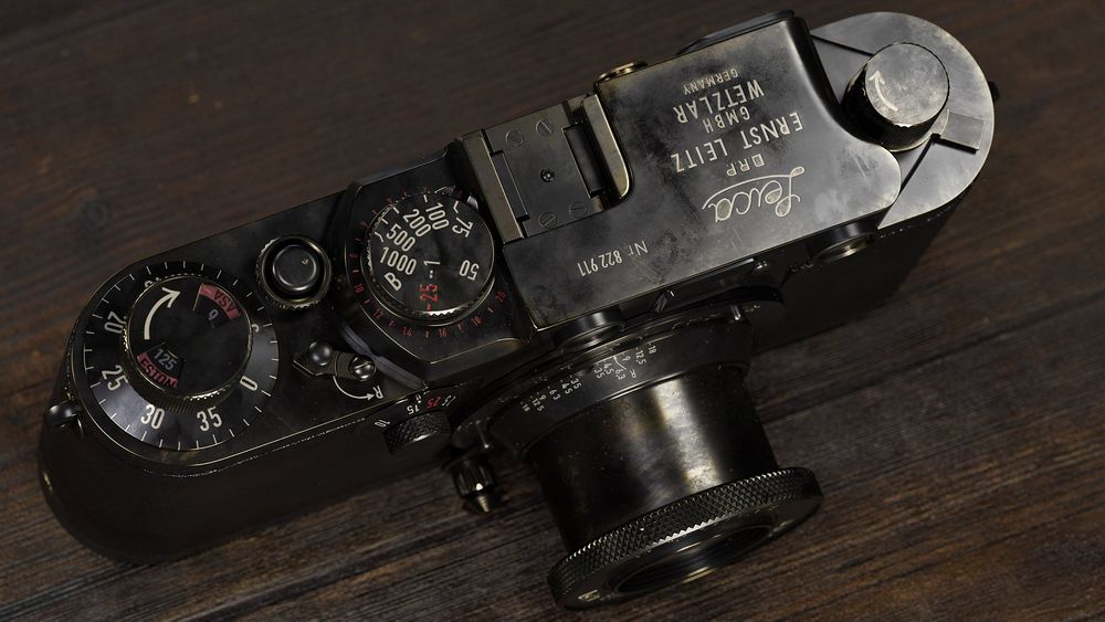
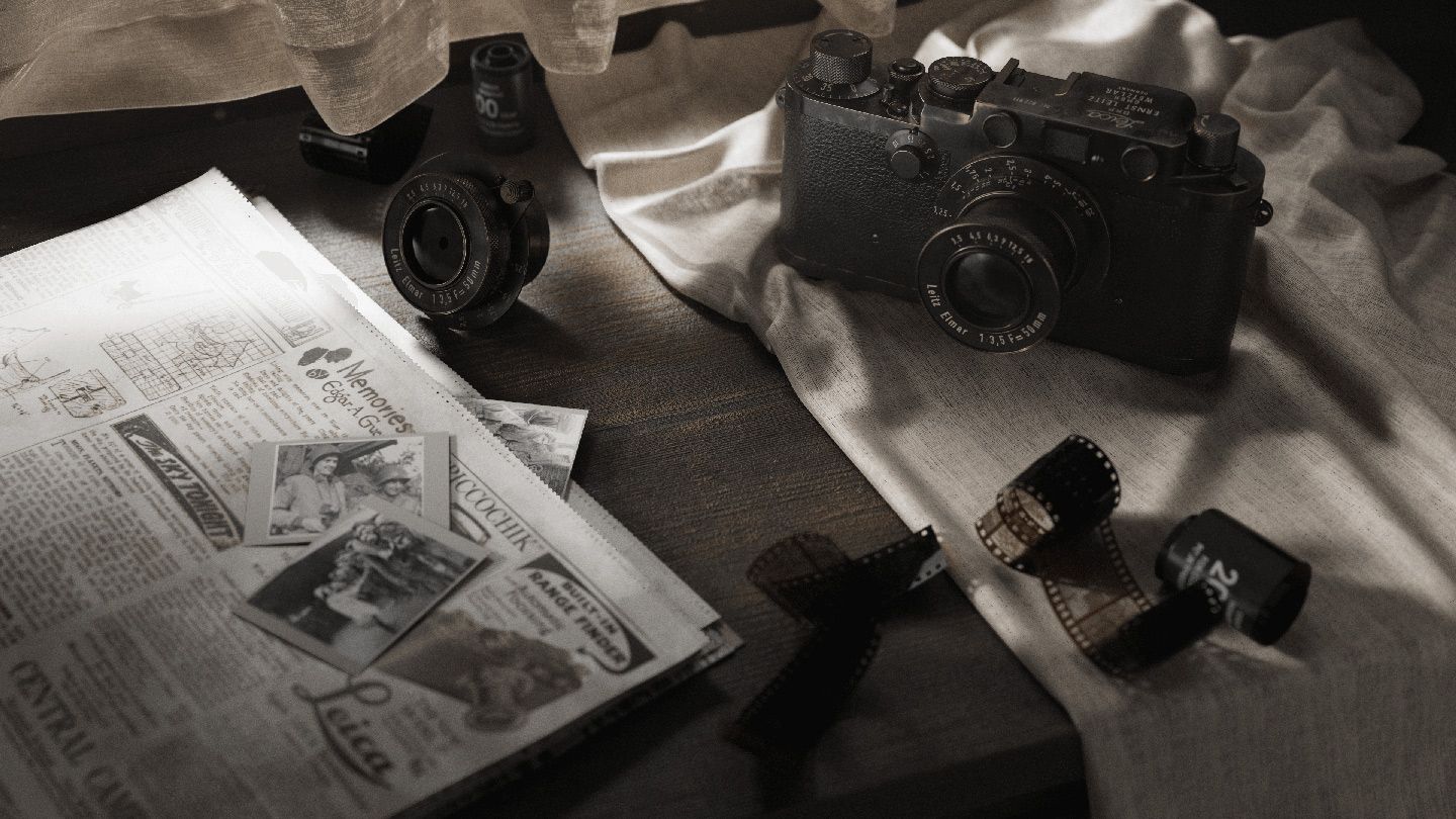
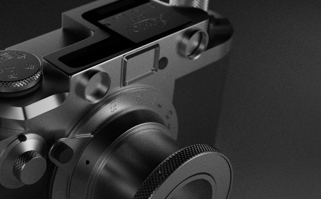
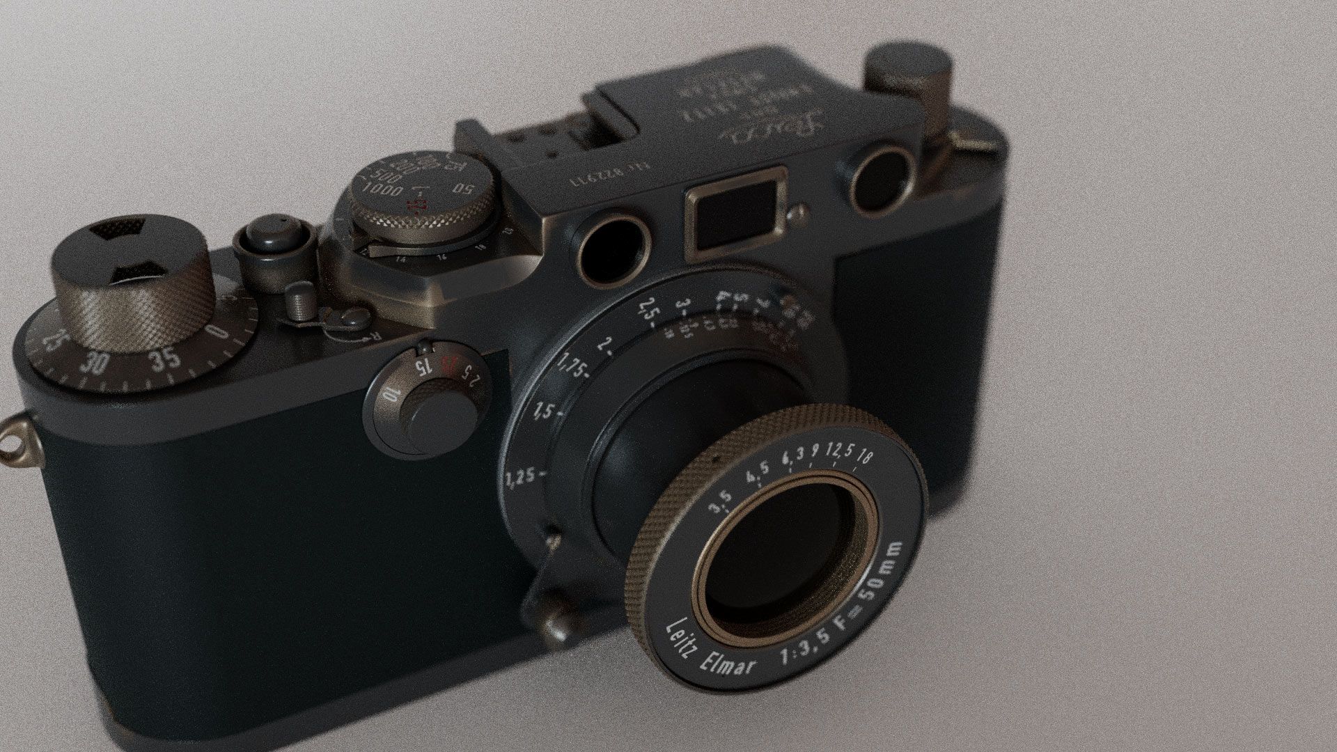
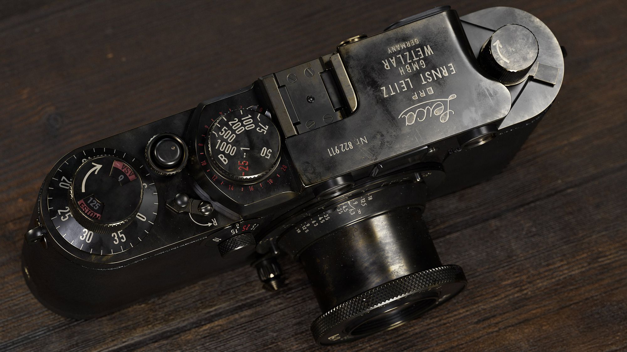
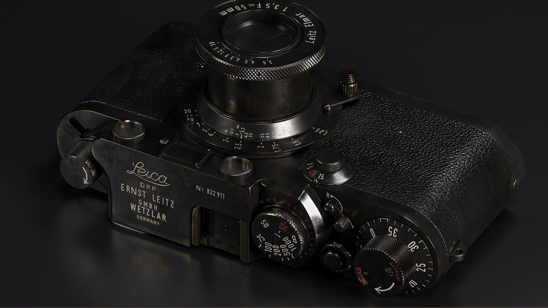
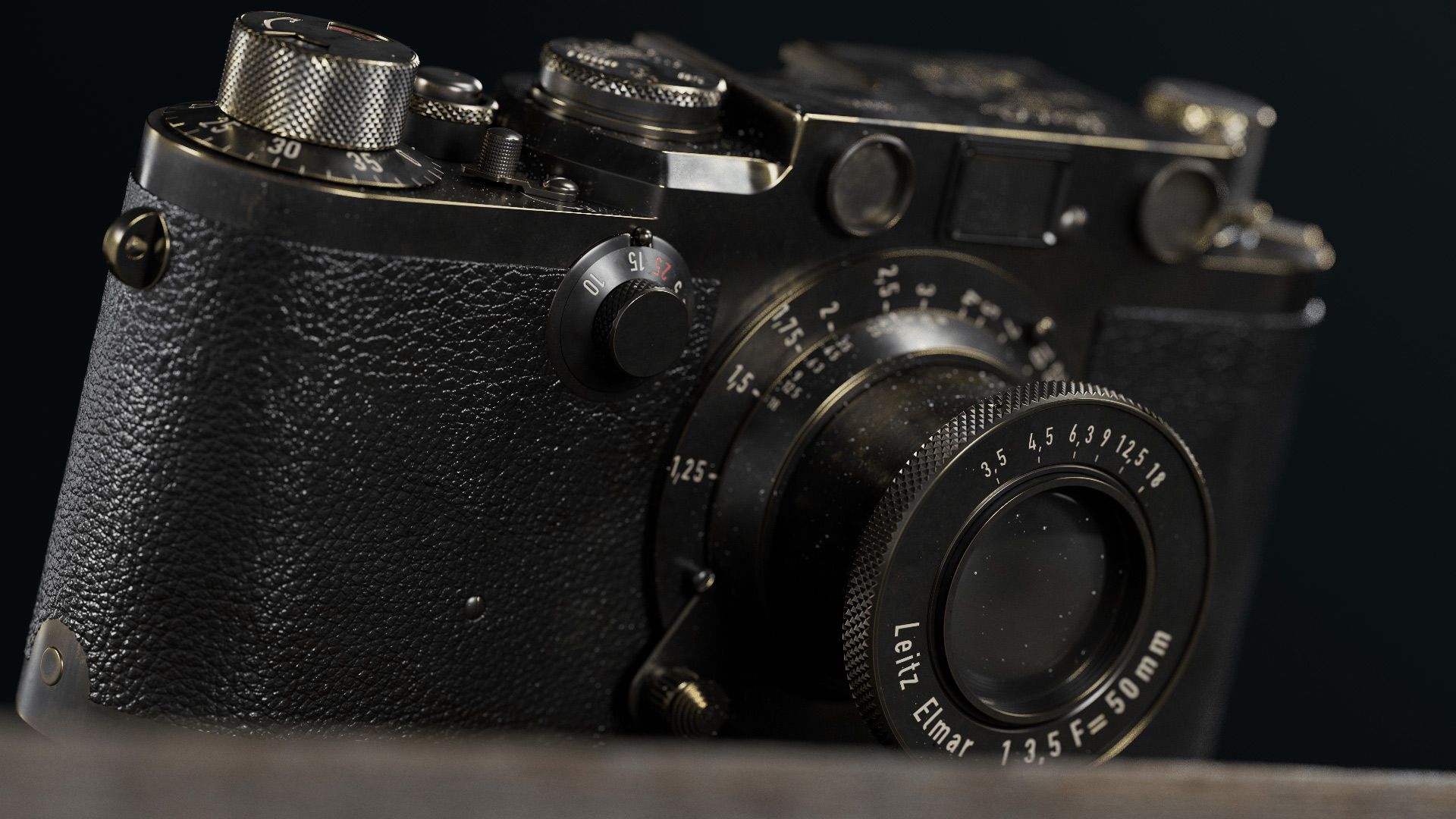
For my second-term final project at Think Tank, I decided to focus on creating a photorealistic scene. Before starting the project, I knew I wanted to make something to showcase hardsurface/organic modeling, photoreal textures, and an understanding of Look Development. With this in mind, I chose to do a still life of the Leica IIIF camera with some cloth and fun shaders.
The Camera asset took 4 weeks to complete, and the composition and environment took 5 weeks to complete. All of the text on the camera is modeled in.
Gathering references is the most important part of preparing to work. It's critical to fill any gaps in your information with some ideas backed by references. Anything ambiguous can add a lot of stress and time to the project. In an ideal world, you would have reference photos from all angles; however, this is not always possible.
For the camera, I was very lucky to find not only images from all orthographic views but also videos describing the different variations of each version of the camera; I also found some incredibly detailed information regarding the specific changes made to this model of the camera versus its brother and sisters of a similar model. I also gathered some images for material reference such as brass and paintware on similar cameras; this can be important down the line when texturing.
Having this reference bank is handy for modeling and can help merge the modeling and texturing processes through specific UVs to speed up the texturing process.
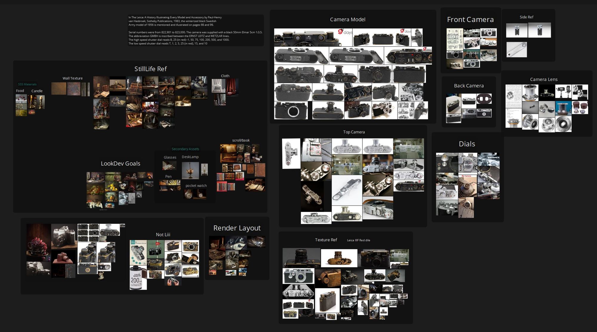
During this phase, I also like to draw inspiration from artists who have done similar projects at an outstanding level. Clement Feuillet & William Fiorentini are both artists I stumbled upon while researching cameras. Their work is extraordinary, and I took heavy inspiration from both their modeling and camera work. They both also did some really amazing work with dust that I wanted to emulate in my project.
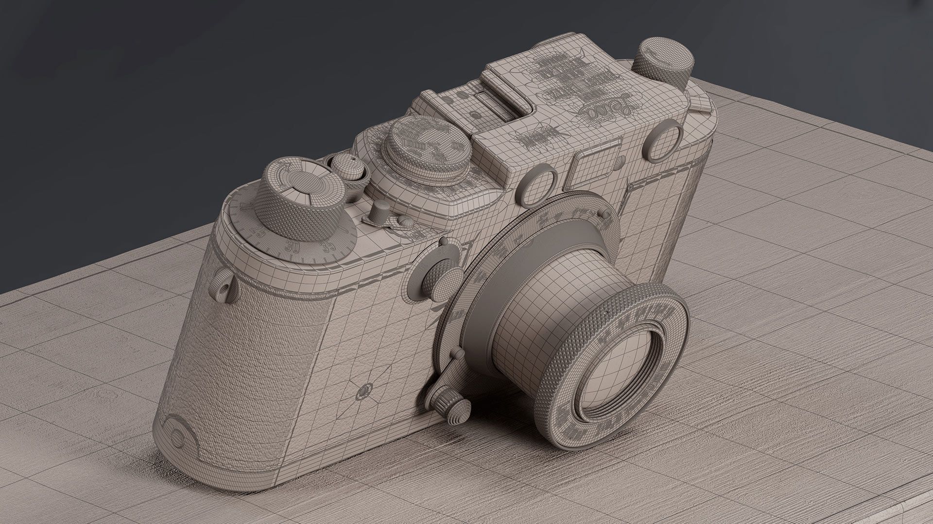
When I work with flat and neat hard surface objects like this camera, I start by blocking out all the flat surfaces. Then, I focus on connecting them together. The most important thing is to make sure that the silhouette of each piece is correct from all angles using the least amount of topology as possible. The camera is a simple shape, so the blocking out process was very short. Breaking things down into parts can often make the trickier concepts easier to wrap our heads around. It's like solving a puzzle - tackling one piece at a time can lead to a clearer picture overall.
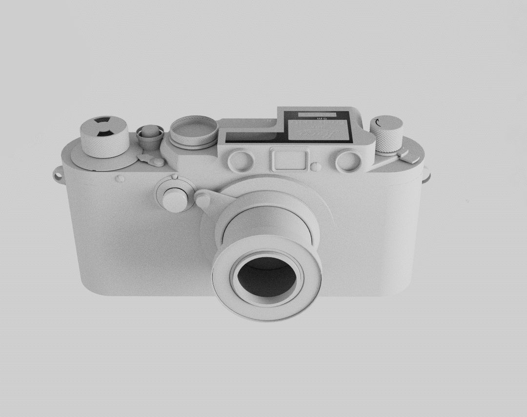
After completing the block-out stage, I began experimenting with subdivision on my model. I focused on identifying and resolving any potential pinching issues. I also planned for bevels to give the model a more polished look. To maintain the edges of the model without adding support loops during the block-out stage, I used Creasing. This allowed me to make flexible adjustments before moving onto the next stages of blockout. Once the basic blockout was complete it was time to move onto polishing the model and modeling in the text.
Because the top of the camera was in cursive, I opted to model it based on reference instead of using a more modular approach. I isolated a flat section of the model and cut out a square piece there, allowing me to work on the text without worrying about it messing up the topology of the camera. I later combined the square cutout and re-worked the topology with termination loops so that the text could fit fine without disrupting the rest of the model.
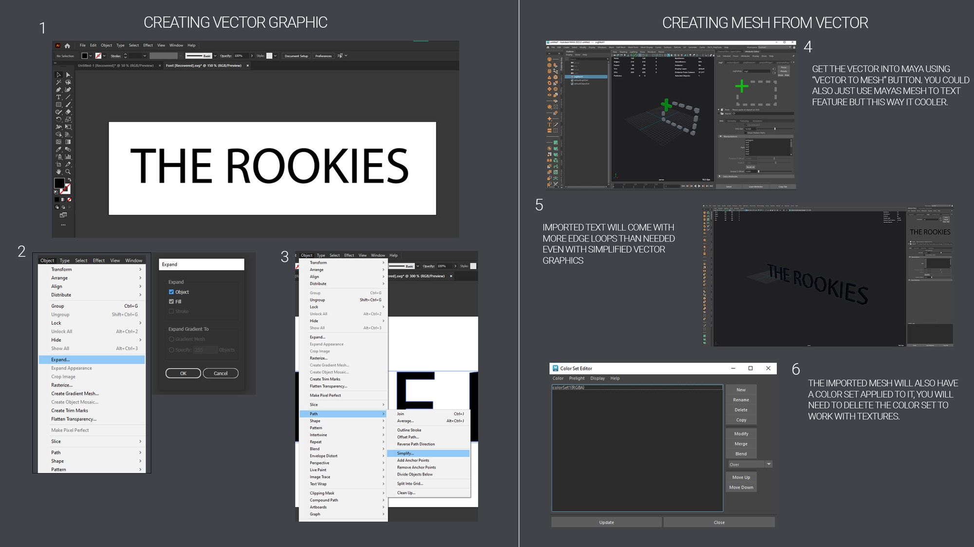
I had a lot of fun creating the modular text! First, I took note of all the text that was on the camera and created an Illustrator text file with it. To save time, I made sure not to include any text more than once. Next, I used Illustrator to convert the text into a vector image. Finally, I exported the text as an SVG into Maya using the SVG to mesh feature.
Once I had the Geometry for the text in Maya; all that was left to do was model it into the camera and clean up the geometry. To make this manageable, I found places where numbers were reused and made sure to do each number one time per dial.
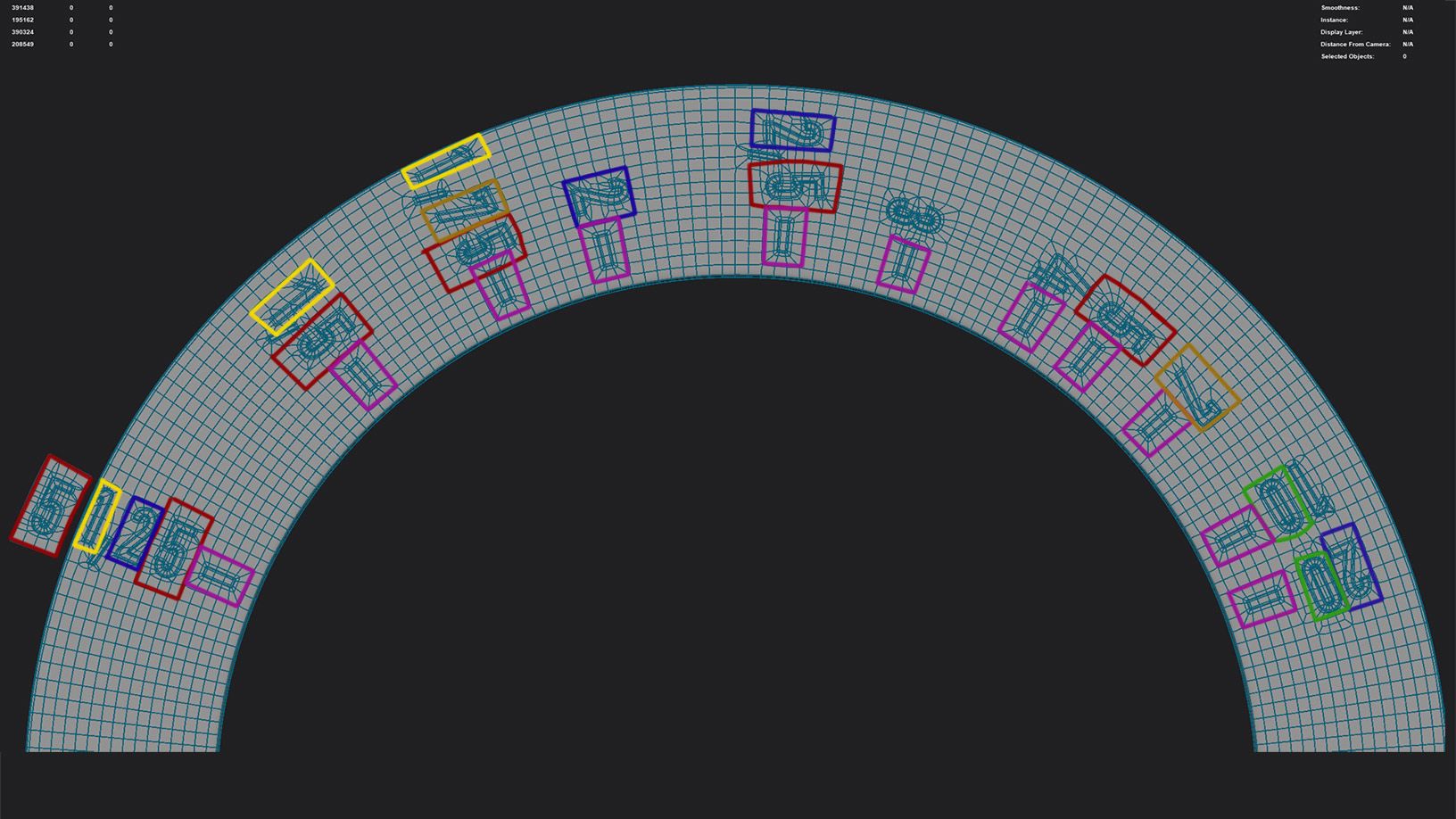
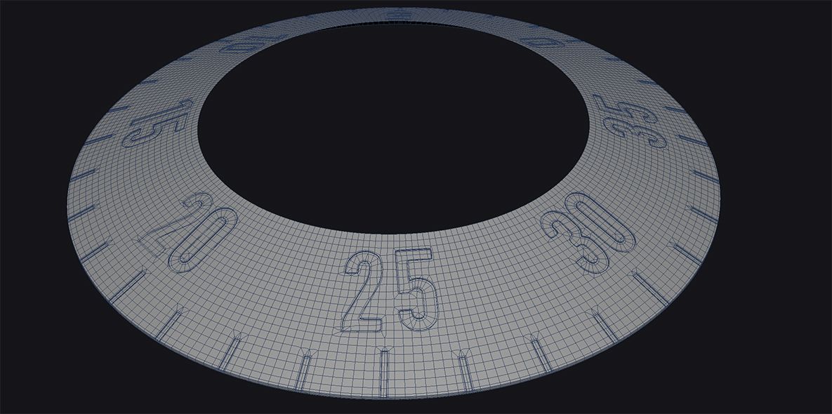
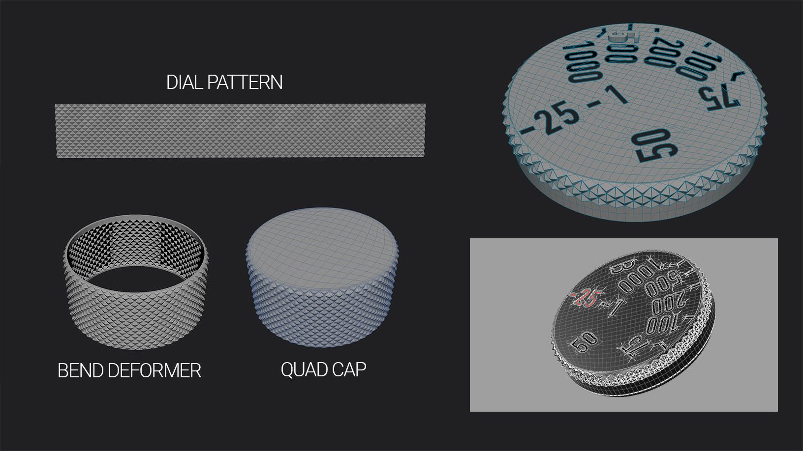
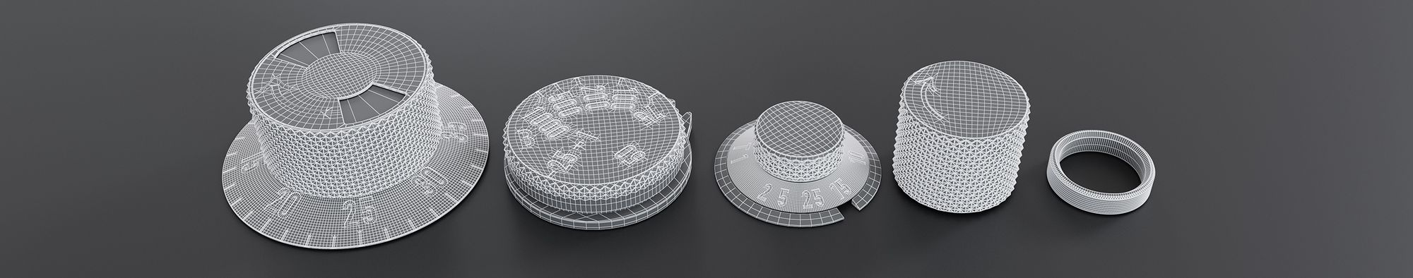
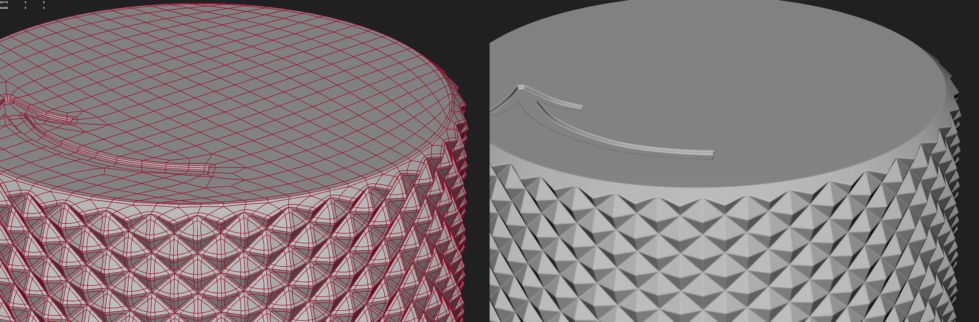
When adding text to any rounded surfaces, it's very easy to get pinching if you don't have the correct topology to support your edges. This meant that it was important to get the starting topology subdivision correct before committing to adding text. Adding too much would make it difficult to work with, and adding too little would give pinching errors. For this, I did a good amount of trial and error for each dial.
To create the dial pattern, I angled a flat plane diagonally and then extruded upward with the faces turned off, offsetting the extrude to fit the angle of the dial. After this, I cut out the text and fixed the topology to subdivide it with support loops.
I finished up modeling after two weeks and started to blockout shaders and start UVs.
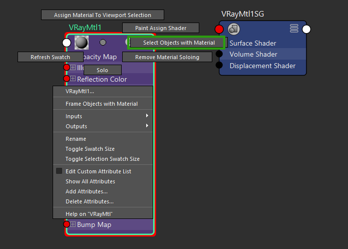
At this point, I had wrapped up modeling and decided to experiment with Maya shaders to help breakdown how I wanted to approach the UVs to best support texturing in Mari. Adding materials to the correct places on the camera let me use them as selection sets (Not exactly selection sets), which made selecting the text much easier for UVs. Instead of manually selecting each bit of text, I could use the hypershade window to select the different materials and planar projection to start the unwrapping process.
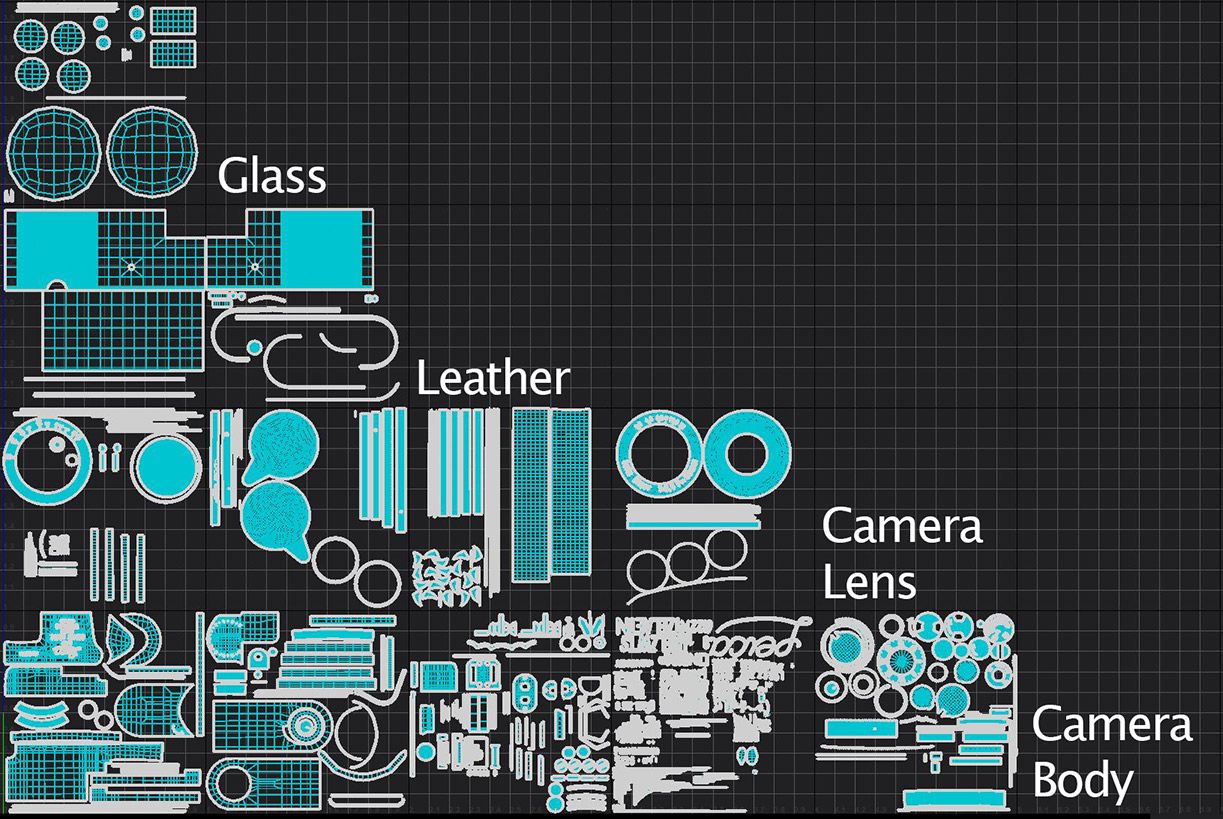
Once everything was Unwrapped, I started organising the shells, the first step is to determine the Texel Density. For this I selected the largest piece of the camera which happened to be the leather wrap. I split the leather into two separate pieces and filled as much space as I could in a UDIM tile. This large leather piece was where I derived the density for the rest of the shells.
For the organisation of the shells I opted to just organise by material with the acceptation to the text, which I organised by colour (White Text, Red Text). Here are my final UVs:
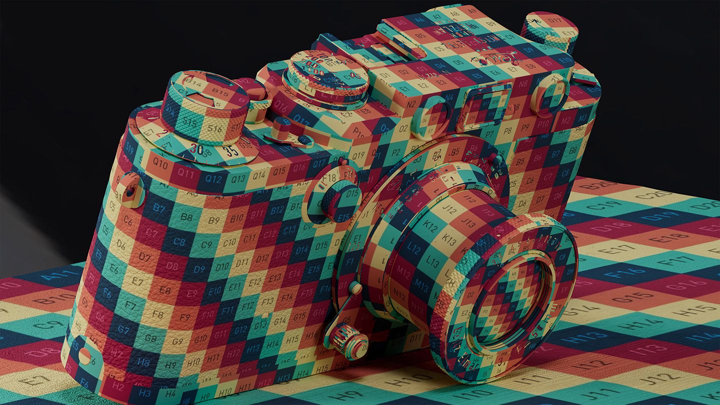
Before I began texturing, my first step was to generate the Geo channel bakes and Mesh maps. For this, I used Substance Painter to create AO and Curvature maps. Afterwards, I imported these maps into Mari as Geo Channels, which I used for creating masks, and simple AO.
In Mari, I started by creating ISO (Isolation) masks for each different material. This allows me to have a mask ready for each individual material whenever I need it. ISO masks are particularly useful whenever you need to mask a specific portion of an object. I also created ISO masks for the numbers on the camera. This is where having UVs properly laid out helped a lot. When organising my UV shells, I made sure to keep all my red text shells in a different location than the white text shells. This made it very easy to drag select all the red text vs. white text.
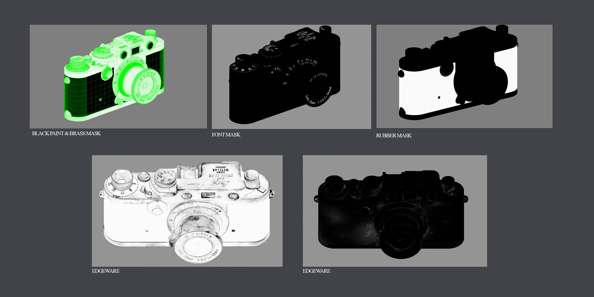
Once Isolation masks are made, I add basic colours to each material and begin building up the texture. I like to start building the texture in layers according to how the material would be built up in real life. For the camera, I started with a brass base and created a layer of paint on top and then finally a dust layer; creating a texture like this allows for the use of masks that dictate where areas of the paint are blended with the brass, where areas of the paint are completely scratched off and allows for more control of dust buildup. Additionally, having a separate controlling mask gives you more to work with in look development, you can export out the mask as a separate channel and use it to to control the IOR of different materials in a blend.
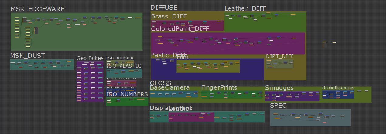
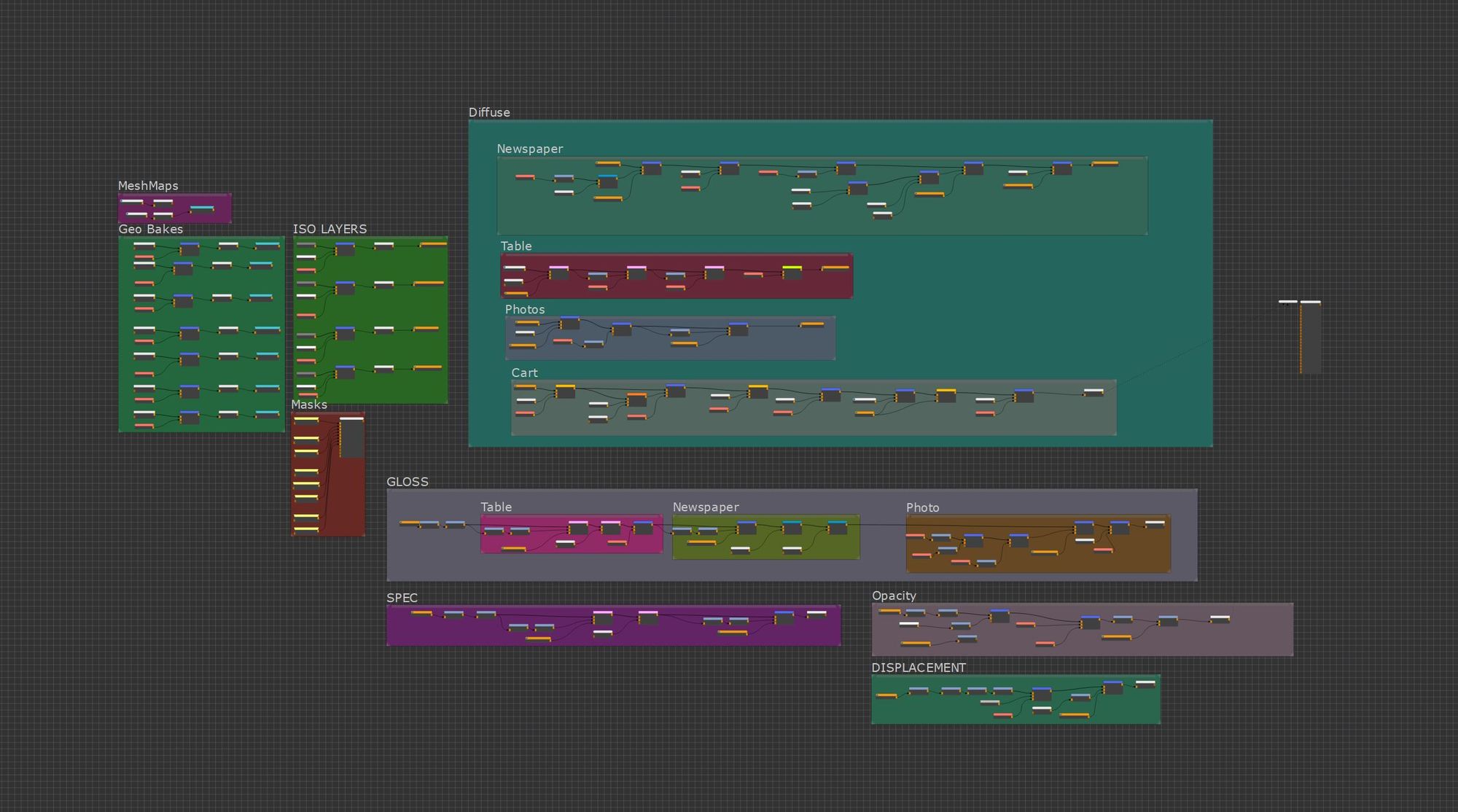
When it comes to texturing, I prefer to use the node graph. It provides a lot of control over each layer and offers nice organisation, allowing me to see each individual map and its relation to the overall texture. The majority of the camera's texture comes from the gloss. This is because the camera paint is almost black. While working on the texture, I spent most of my time either painting the edgeware mask or adding details to the gloss.
I finished my initial texture pass to as quickly as possible in order to work on both the look development and texturing simultaneously. Texturing the camera was very simple and took only a couple days to finish. I continued to modify the camera textures throughout the rest of the project whenever needed to bring out details.
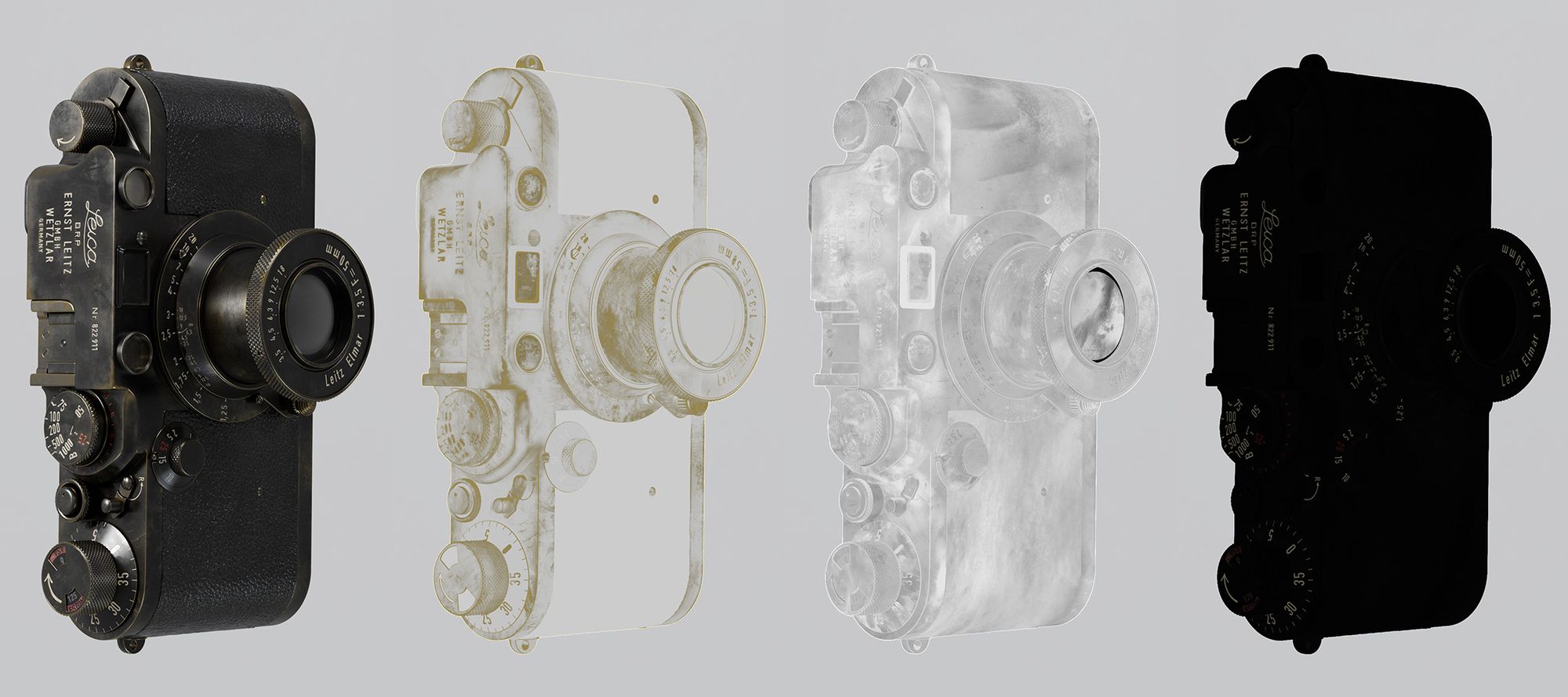
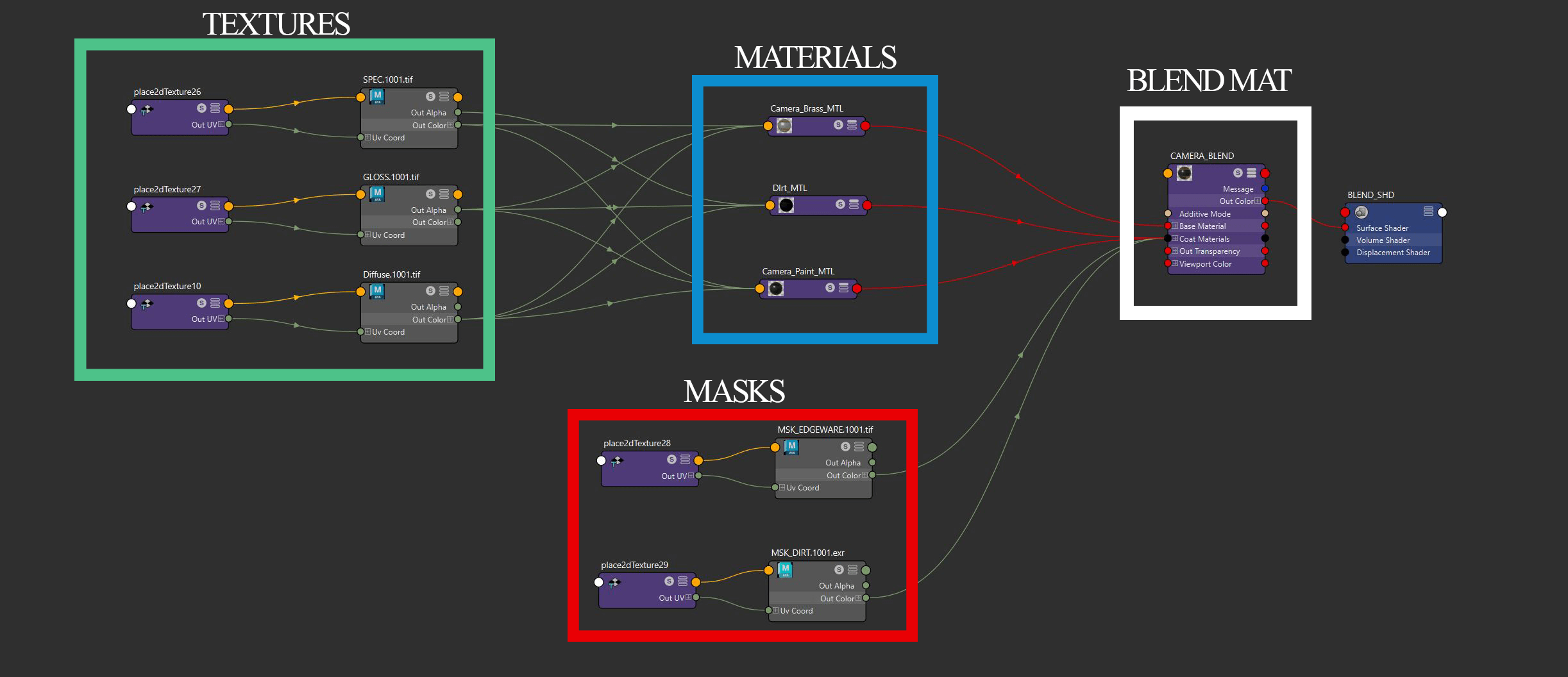
In my camera's look development setup, I use a single blend material that transitions between three different materials. The initial material is brass, which differs from other camera materials by its higher Index Of Refraction (IOR). Above this, there is a paint material blended using an Edgeware mask from Mari. Lastly, there's a layer of dirt and dust positioned on top of the paint, which has a lower IOR and is controlled by a Dirt mask.
Once I had the texture in a good place, the last thing I did was add the final touches to finish off the camera renders.
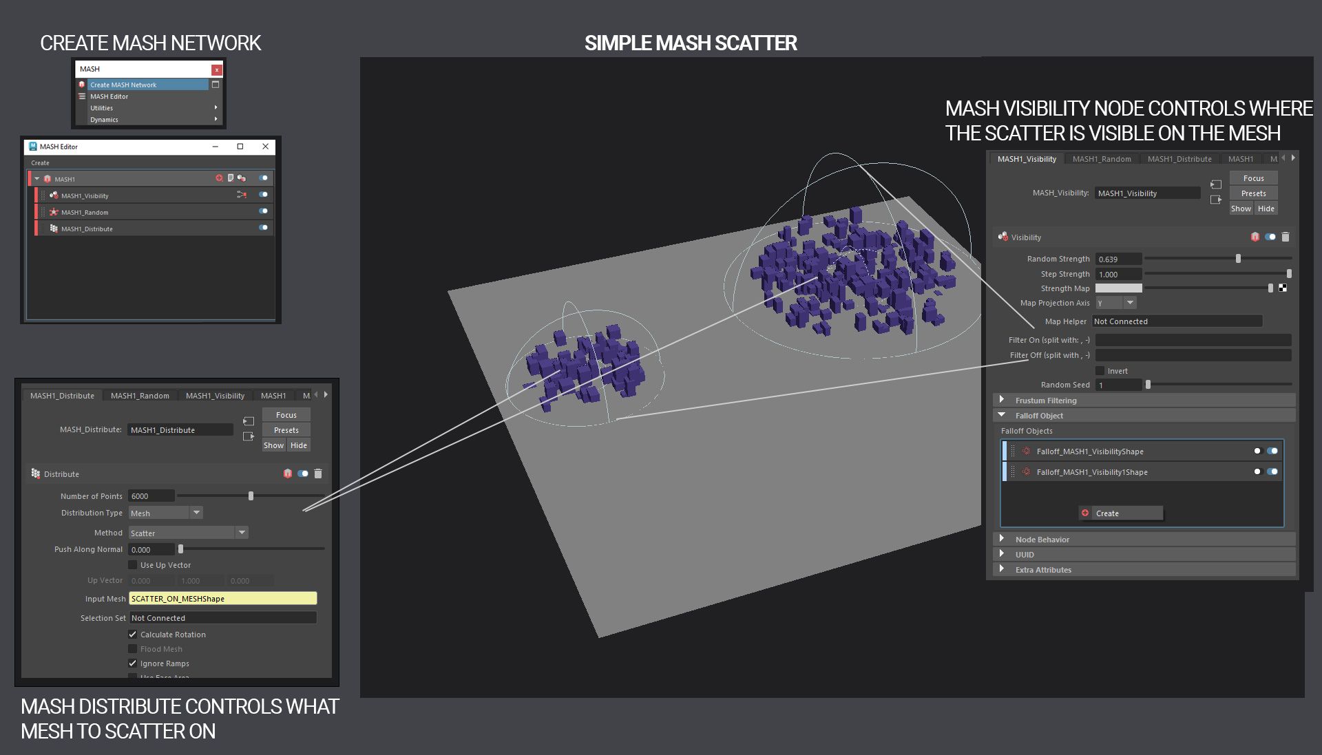
For the dust, I used three different methods of scattering. The first was with MASH. Mash is an internal plug-in available in Maya, its very helpful when doing things that involve motion graphics. MASH also has some features for scattering objects on surfaces. I used this to create more uniform scattering across the scene.
While MASH was decent at scattering dust around the camera, it lacked a more artistic appeal. To fix this issue, I manually placed quite a bit of dust in areas where MASH struggled. You can do this in many different ways, I used spPaint3d to do some quick manual scattering.
These two ways combine procedural and manual scattering but lack something. They feel either too procedural or too manual and don't do dust justice! The last method for dust scattering that I used fixes both of these issues.
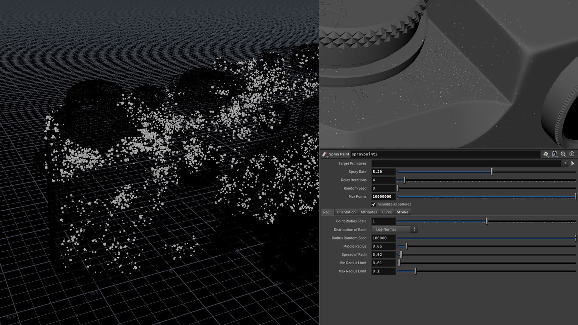
My supervisor showed me the best and last way I used to scatter. With the Spray paint node in Houdini, you can paint anywhere you want and automatically get a random scale to each point. Because everything is built-in nodes, adjusting the dust is very accessible and non-destructive. With this workflow, you can integrate, remove, and modify any dust assets whenever needed, making it very easy to work with. After all the points were scattered on the object, I populated each with dust geometry.
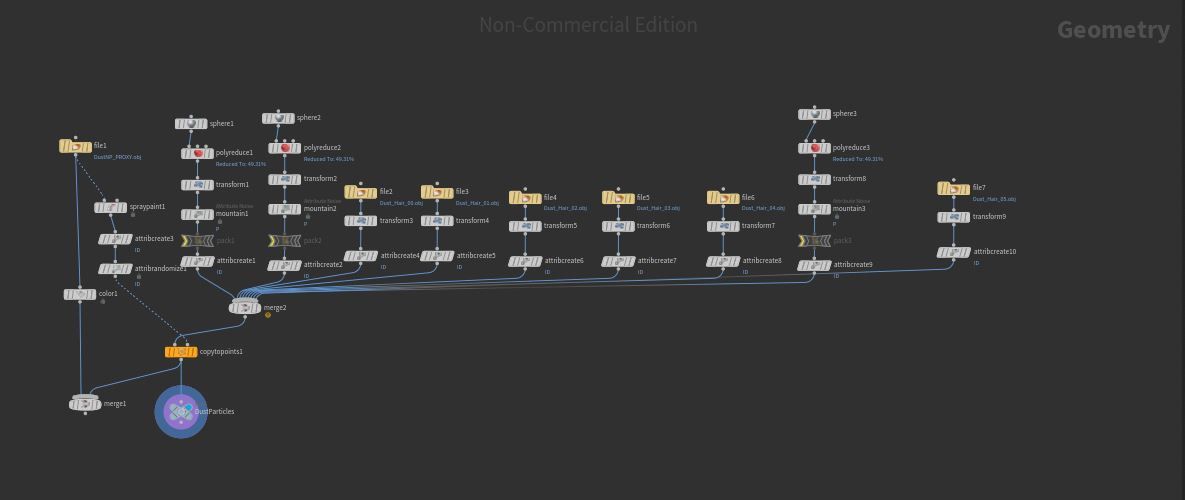
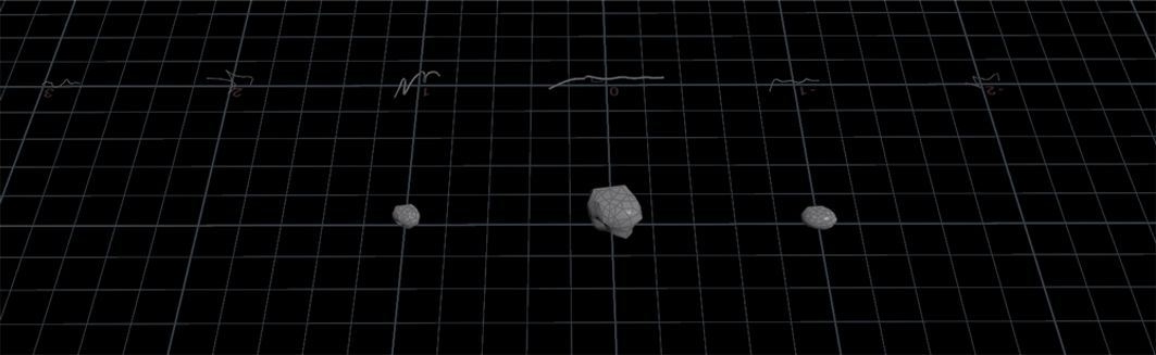
I used two different types of dust. The first was created directly in Houdini; I started with a sphere node and then used a transform node to adjust the scale and a Mountain Node to give the dust the correct shape. The second type of dust was spline-based. For this, I opted to purchase Timothée Marons dust spline pack, onto which I just extruded basic cubes. I then gave an attribute ID to each dust and linked it directly with the spraypaint node for scattering.
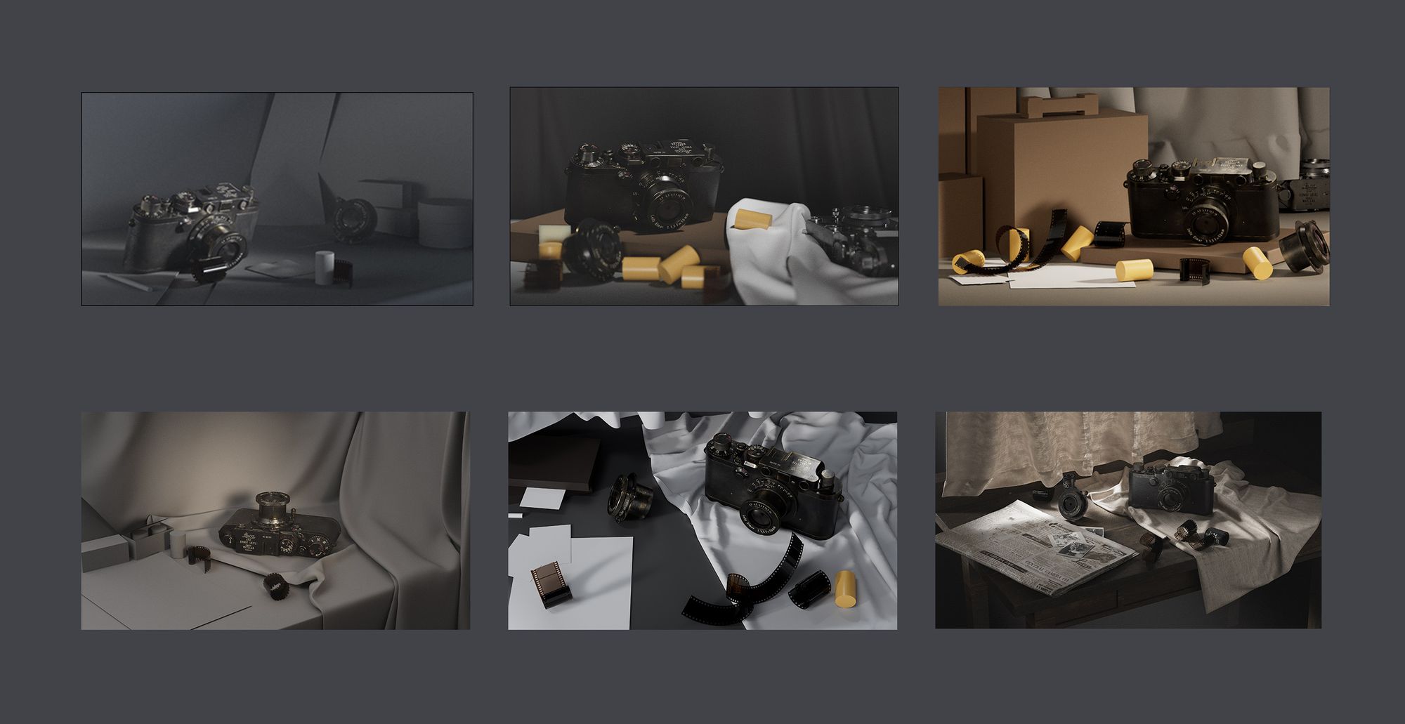
Figuring out what goes in the environment was the first step in the process. I had many different ideas about how to present the scene. This was by far the most difficult and time-consuming part of the entire project. After this, I have such a huge respect for still-life composition.
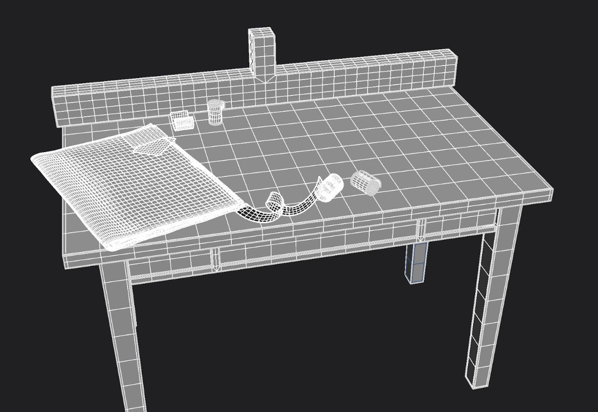
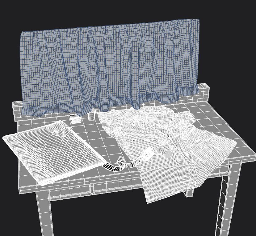
Once I had a composition roughly blocked out, I began to refine all the modeling. For the newspaper, I poly-modeled the basic shape and used MASH to create an array of newspaper pages inside I then sculpted on top of this in ZBrush to add some basic variation to the model, the rest of the props and models are simple shapes. I used Maya's nonlinear bend deformer to create the rolls of film.
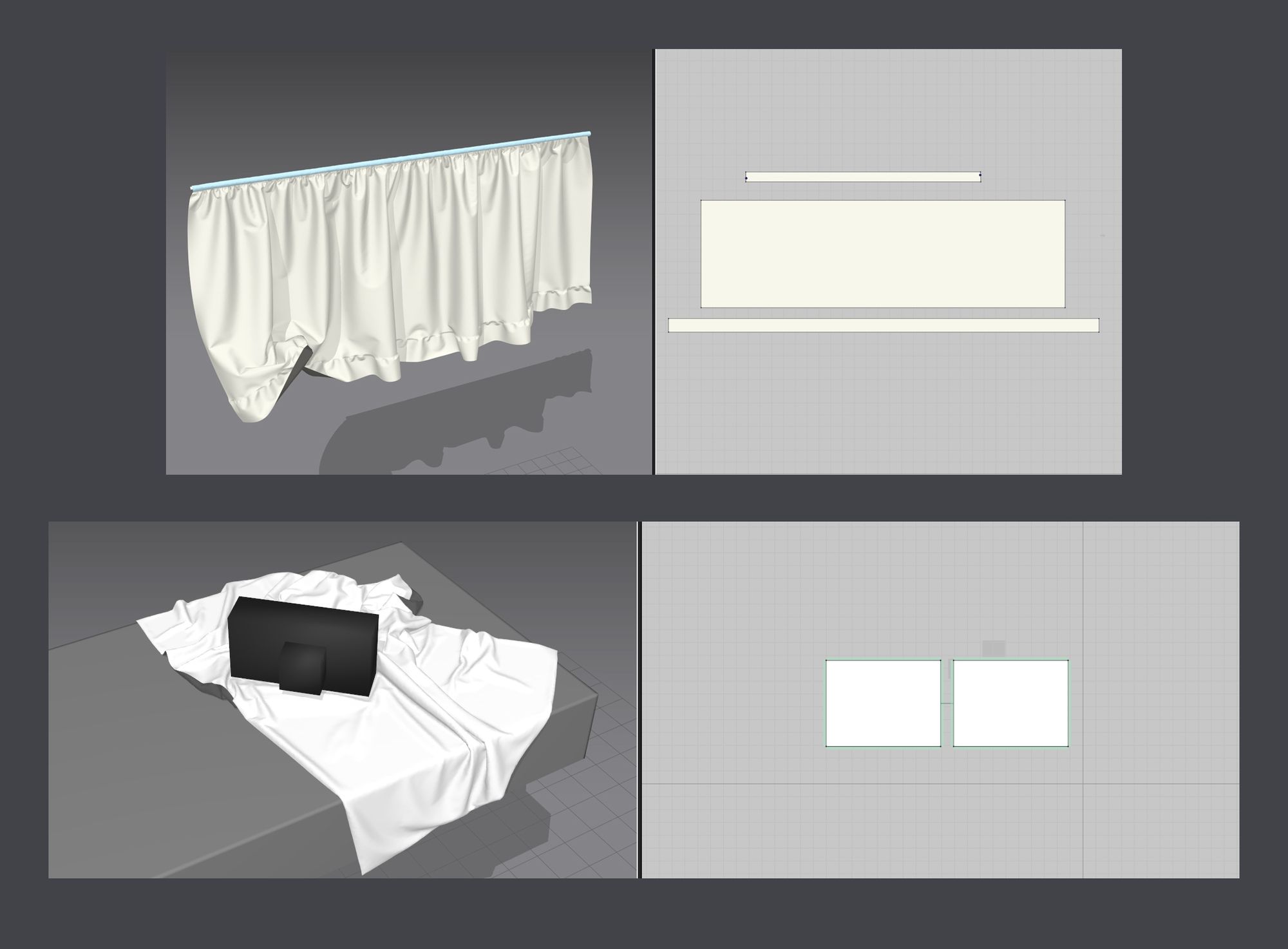
Both the tablecloth and curtain were created in Marvelous Designer. The pattern for the tablecloth was a square, which was simulated on top of a proxy table. I messed around a bit with different cloth types and simulations to get a base with a high particle distance that I liked. Once I had a decent shape, I used the copy-over feature in Marvelous to generate sewing for the second layer of cloth and then re-simulated at a lower particle distance
The Curtain was a separate simulation around a cylinder and draped downward onto the table the overall process was the same as what I did for the table, start with a high particle distance and narrow it down till you have something that looks like you want.
I really enjoy cloth retopology, it takes advantage of some very cool techniques in maya. For this, I first created UVs using the UV editor viewport of Marvelous Designer; if you right-click in the UV editor window and select reset to 2D arrangement, you get a copy of your pattern as UVs. Once I was done with the UVs, I created two different versions of each simulation - one flattened and the other simulated. After that, I exported both versions to Maya for re-meshing. The best thing about doing retopology this way is that the flattened and simulated cloth share identical UVs, which allows you to transfer attributes to create your cleaned mesh.
To begin, you will need to create a clean mesh with quads on top of the simulated flat mesh. This can be done by making the flat mesh live and using quad draw on it. Once you have a clean mesh, transfer the UVs from the triangulated Simulation Flat onto the New Clean Quaded Flat. Don't forget to delete the history after transferring attributes. Its also important to note that when you transfer UVs your geometry needs to be ontop of one another, this is because we are transferring UVs based on Vertex space.
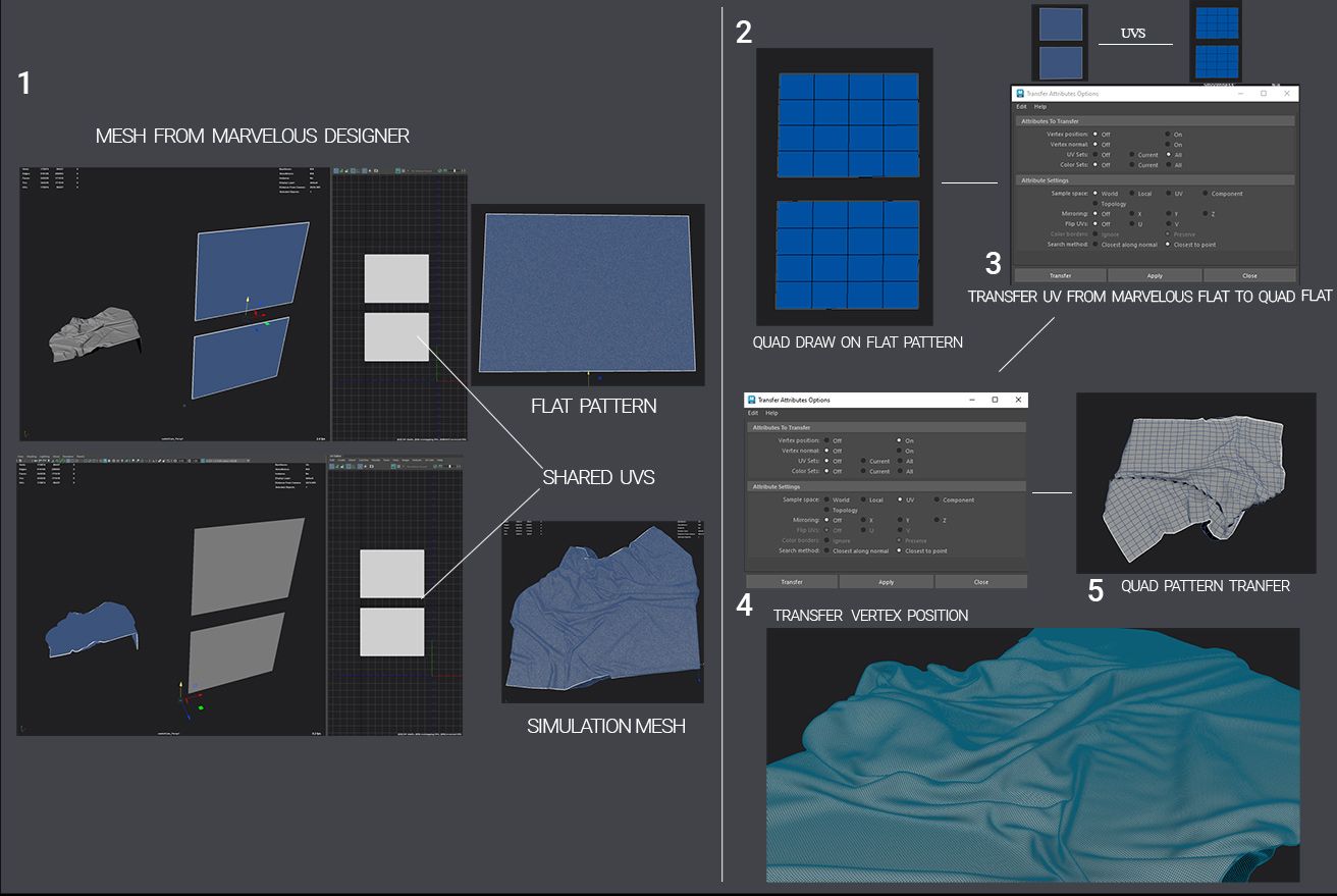
Now that the Quaded flat and the simulated Triangled mesh from Marvelous share the same UV space, we can easily transfer the vertex positions of the Quaded flat onto the triangulated simulation. This can be done by changing the Transfer Attribute settings to sample vertex positions from UV space. After that, we just need to subdivide the Quaded mesh and transfer attributes until we are left with a high poly quaded version of our triangulated simulation. This is a very cool workflow and there are plenty of videos available that explain it in more detail. Check out the video by Flipped Normals if you want an in-depth explanation.
This method also leaves us with a nice uniform UV shells to work with, I used this to my advantage when texturing the cloth. Here is a look at the final topology of the environment scene, it's very simple geo just enough to support what we need.
Texturing the cloth was very simple, I found a cloth texture that fit what I needed online. I created a tiled version of the cloth and then created different maps from it. I used Photoshop to convert my texture into something that could be used as an opacity mask directly in Maya. With the opacity mask and base tile texture all that was left to do was create an interesting shader. I used a blend material to blend between 3 different colours of cloth with fractal procedurals to break up the colour variation.
Texturing the rest of the assets was very similar to texturing the camera, I started with a base texture and built it up till it resembled what I was looking for.
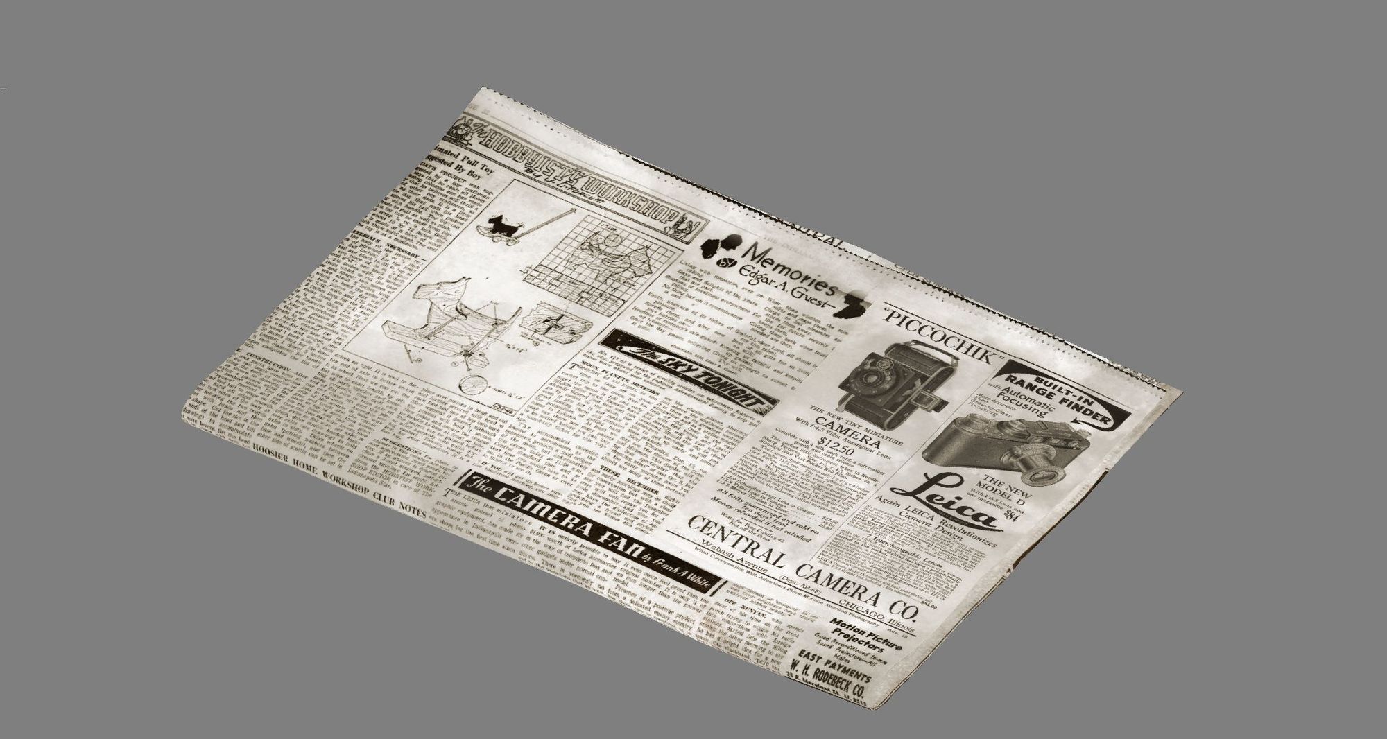
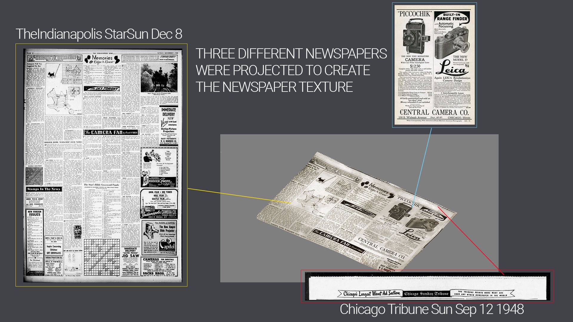
The newspaper texture is the result of a few different photo projections; I found images I liked from multiple different Leica articles from the time period, colour-corrected them, and stitched them together to fit the newspaper. The other pages of the newspaper are low-resolution versions of the Chicago Tribune article; they were also used to create the opacity mask for the frayed edges at the top of the paper.
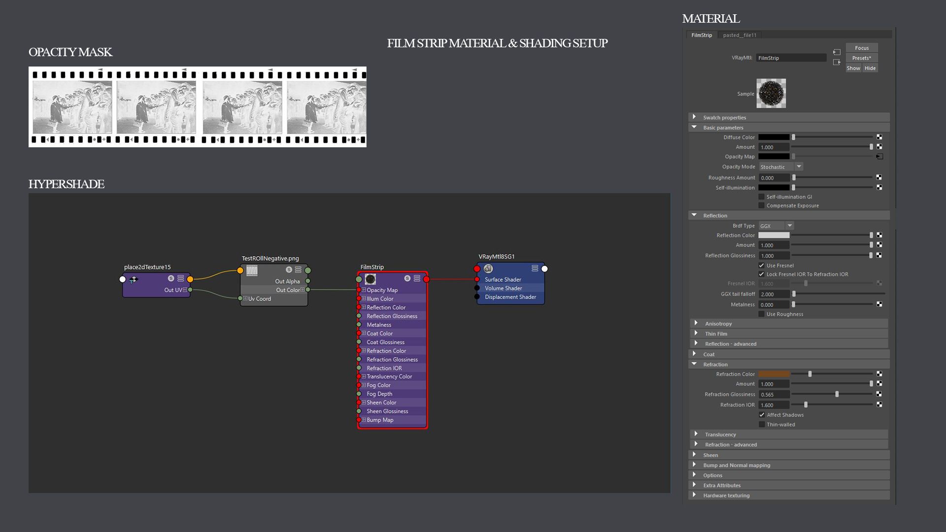
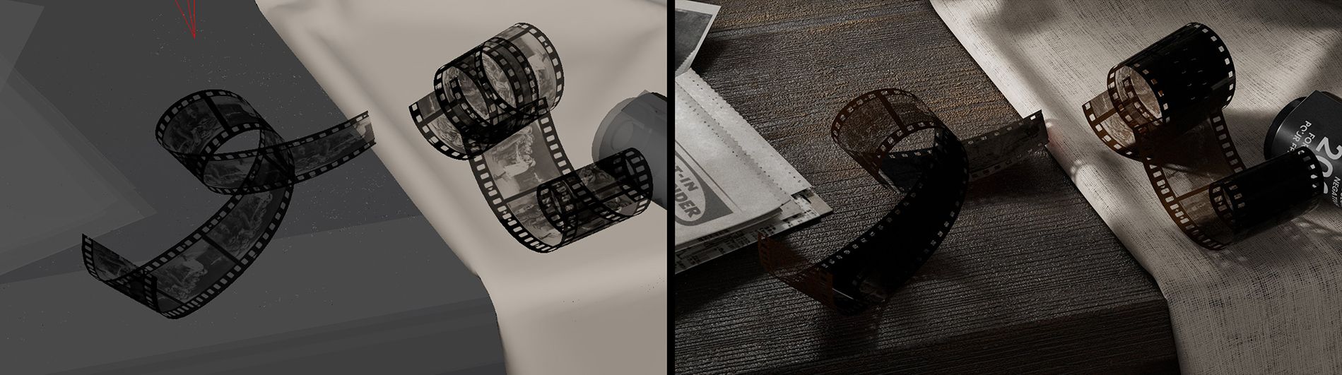
The film strips were a combination of shader and Photoshop work. To start, I found an image of a film strip online and created a black-and-white mask to control the opacity in Maya. By changing the refraction colour of the shader in Maya, I was able to get an interesting colour for the light refraction through the film. The last step for the film was to add the image onto the negative.
The last and final step to the scene was to create interesting lighting, finalise camera settings, and do any post-production. The first step is lighting. I used Nuke to adjust and map out any changes in light values through grade and level nodes. You can adjust each light individually using the shuffle node and Multichannel EXRs.
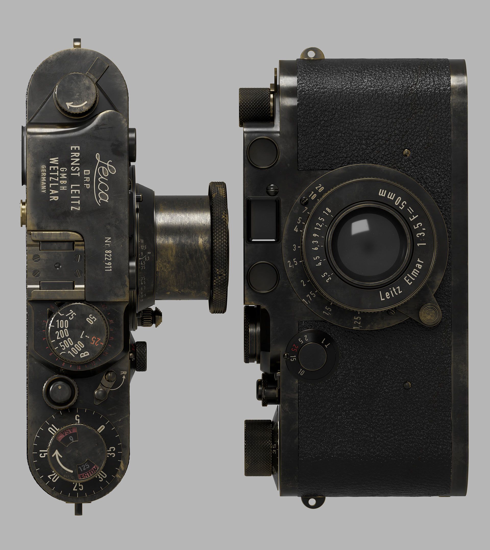
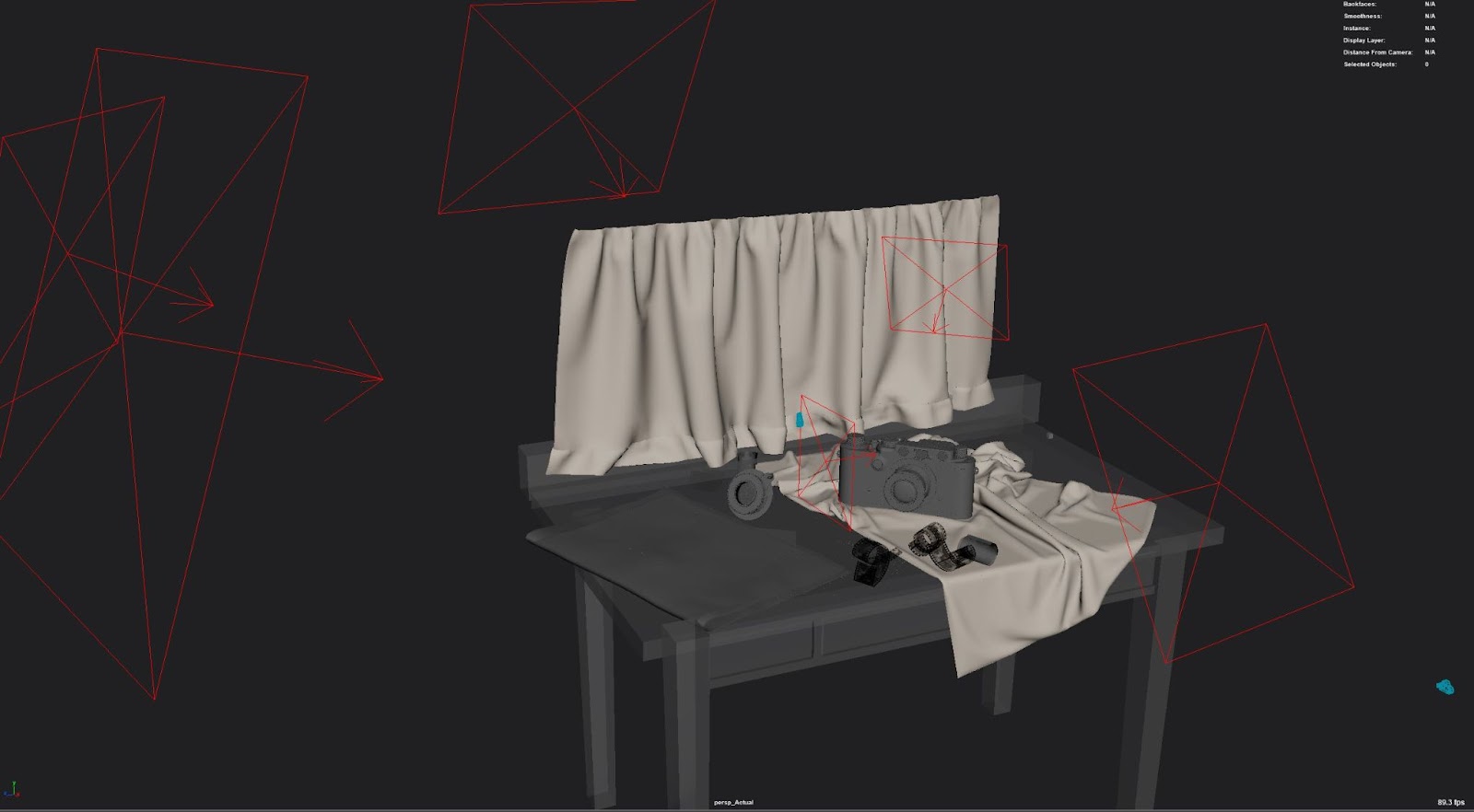
For the lighting, I used simple rectangular lights. I try to keep things as simple as possible and only add lights as needed. I always start with a three-light setup a Keylight, a fill light and a rim light, in this case, the rim light was changed to be more of a reflection light to highlight the gloss of the camera. The goal for the lighting was to make sure all the shadows were nice and soft, to do this all you need to do is decrease the intensity of the light an increase the size of the light.
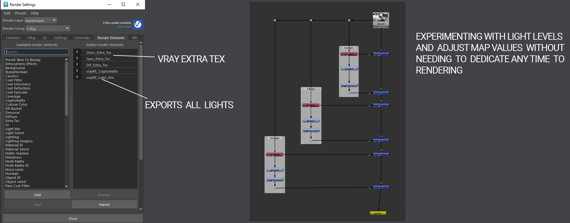
This is a setup for adjusting the AOVs of a multipass EXR in Nuke. I also used Nuke to render my final composites and breakdowns using a similar method. Shuffle nodes are extremely useful and can speed up post-work dramatically.
I did a couple of passes of lighting and worked directly with light linking to ensure everything was lit in the intended way. I also did a quick environment fog pass to add depth to the scene.
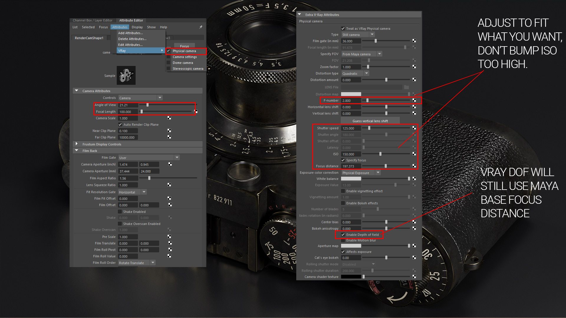
Finally, for the camera settings, I always like to do a few quick things.

Thank you so much for taking the time to read about my work! And thank you to The Rookies for giving me the opportunity to show it. Feel free to reach out to via my Rookies profile and connect if you'd like more information on the project or want to talk 3D.