How to Integrate Realistic Assets with FX Simulations into Live Footage
VFX (3D) Master graduate from Escape Studios in London, Camila Valencia, shows us how to integrate realistic assets with FX simulations into live footage.
VFX (3D) Master graduate from Escape Studios in London, Camila Valencia, shows us how to integrate realistic assets with FX simulations into live footage.
VFX (3D) Master graduate from Escape Studios in London, Camila Valencia started her journey in the animation environment back in 2014 when she was introduced to an ‘Animation and Games design’ course and fell in love with 3D.
From the beginning Camila has been involved in every step of the Animation/VFX pipeline from creating illustrations to compositing the final outcomes, and especially enjoys creating realistic hard surface models and texturing them. In this article Camila shows us how to integrate realistic assets with FX simulations into live footage.
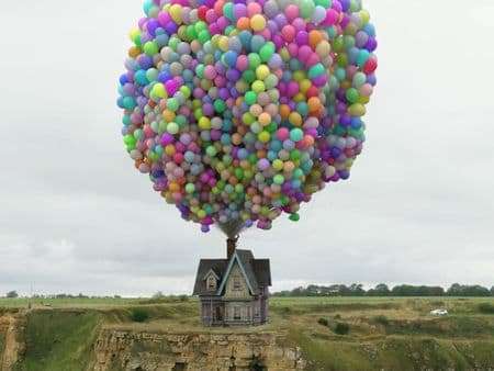
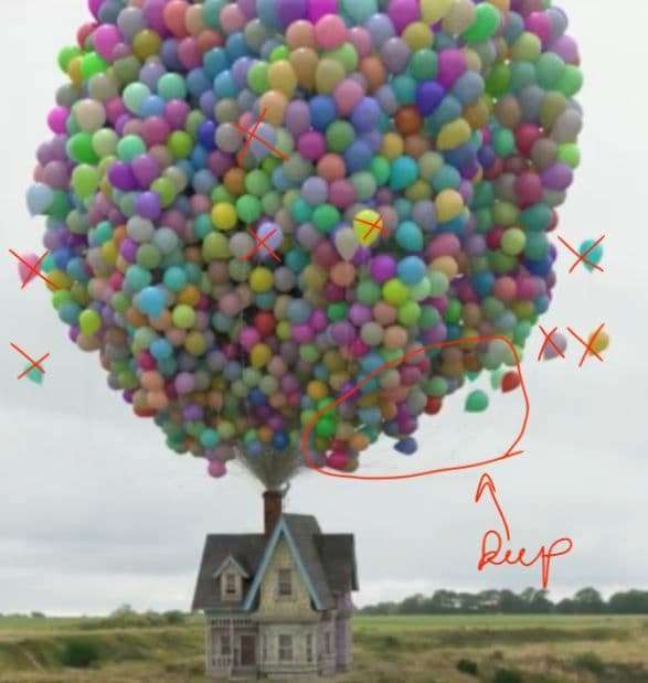
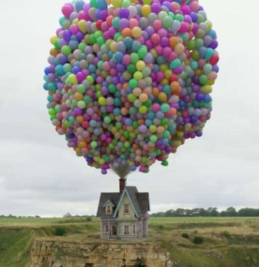
In this article I will walk you through the process I followed replicating a realistic version of the house from the Pixar movie “Up”, with emphasis on the tracking and creation of the balloon simulation, to creating my final major project for my VFX (3D) Master degree at Escape Studios.
The requirements of the project were to create a realistic piece of work, have FX elements in it and integrate the 3D elements into a live drone footage.
I will talk about the following software:
To model the house I collected references from the movie, watching the ‘making of’ documentaries (Pixar Animation Studios) where the creators talk about the process they followed. Additionally I collected information from the internet such as the floor plans of the house.
This helped me to achieve a realistic look since I had a very clear view of what needed to be modelled, what the textures would look like, and the dimensions of the house.

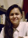
For the balloon simulation I researched different methods I could apply to achieve the best results. I had two options, either use Maya with nCloth or use Houdini with Vellum. As I was not sure which option was best I did tests with both and made a pro-con list to compare and choose what was the best option for me.
Due to covid-19 I was not able to shoot the drone footage myself, therefore I had to find drone footage online. I visited many stock websites and encountered the issue that most drone footage was not free to use and I would have had to pay a large amount of money. Fortunately, I found Pexels, which is a website where people share their videos and images for free and in return ask for credit or a donation.
I wanted to integrate the 3D elements in an environment similar to the movie’s environment, ‘Paradise Falls’. To find this, I searched through several drone footage that contained cliffs until I found one that would allow me to show the house both from up-close and also from afar to enable the balloon simulation.


An issue encountered with online footage is that in most cases, the information about the camera used is not shared, this information is very important to achieve an accurate tracking of the video.
To track the footage I used 3DEqualizer. As mentioned before, it is important to know the information about the camera and type of lens used to achieve an accurate tracking. I was lucky that the videographer who shot the footage replied to my email with the information I needed.
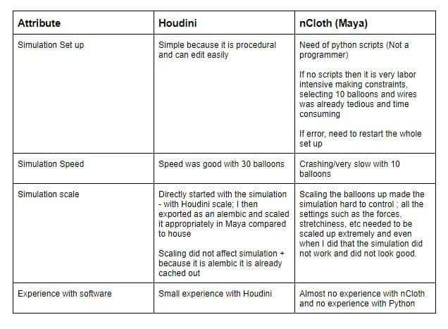
When the footage is imported into 3DEqualizer the first thing to do is to set up the lens information:
One thing I learned is that if the camera lens is equivalent to 35 mm the best way to achieve the right aspect ratio is to set the 'Pixel Aspect' to 1 Fixed, 'Film Aspect' to 1.777, 'Filmback Width' to 36 mm Fixed and the 'Filmback Height' to 20.25 mm Passive. If the focal length is known, type it in and set it to Adjust, this will give the software room for error during the Focal Length calculations.
When tracking footage I always have in mind that the more manual tracking points I place the better the tracking will be. Make sure the points don’t jitter too much because this will cause problems when doing the focal length calculation. Another thing to have in mind is not to track reflections and moving objects because that would adversely affect the tracking.
I placed more than 40 manual tracking points mixing between tracking ‘markers’ and tracking ‘patterns’ points. When placing these points I made sure to have a good point spread, which means that the points I was tracking were spread evenly in the footage and not concentrated in one part of the footage.

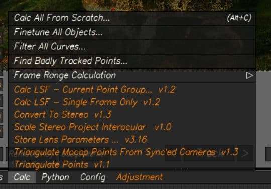
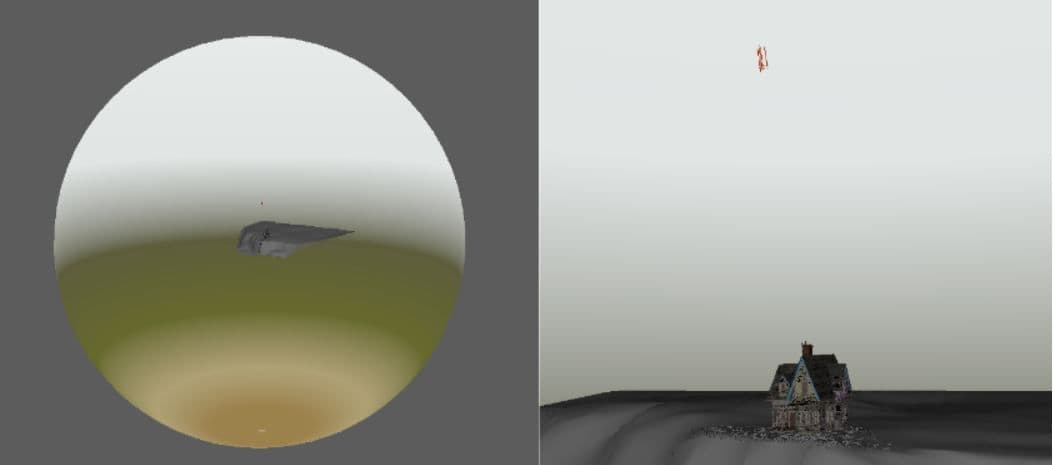
Once the tracking points were placed the calculations needed to be done. To do this, I clicked on ‘Calc all from scratch’ which makes a window pop up displaying the camera movement (red line) and the tracking points I had placed. As I was happy with it and didn’t notice anything wrong, I clicked on ‘use results’.
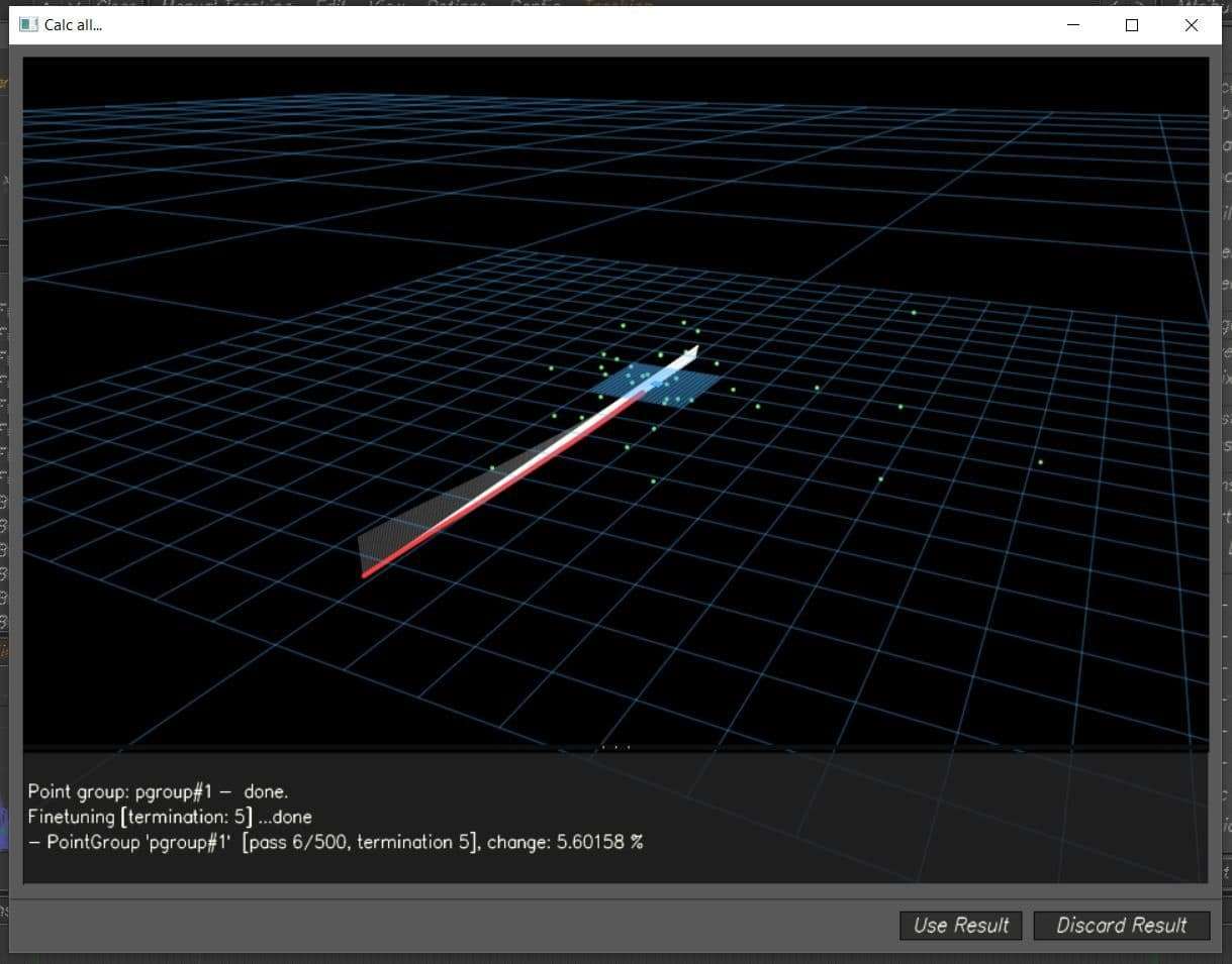
By using the results, two green lines appear on the timeline. These lines indicate that the software had calculated the camera movement on the frames between them, so the wider apart they are, the better the calculation is.

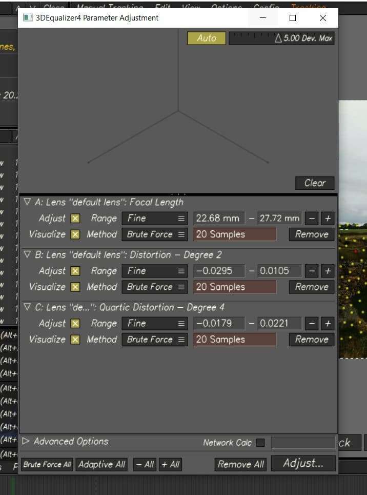
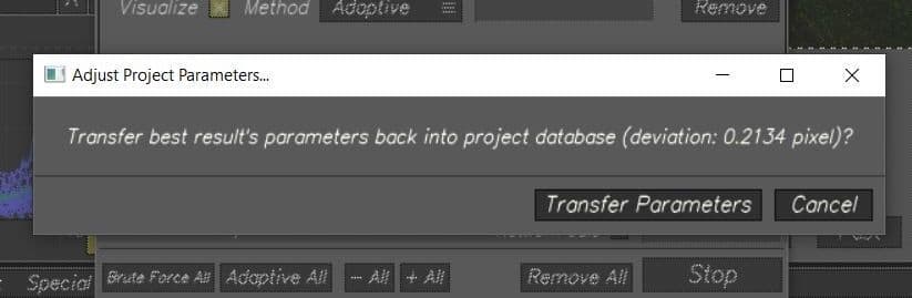
The next step was to calculate the Focal Length. I opened the Parameter Adjustment Window and set all the lenses to ‘Fine’ range and ‘Adaptive’ method. This gave me a deviation pixel of 0.2 and a Focal length of 23.6 which is a great result because the deviation is under 0.8 and the focal length is pretty close to what it was in real life. As I was satisfied enough with the calculations, I clicked on Transfer parameters.
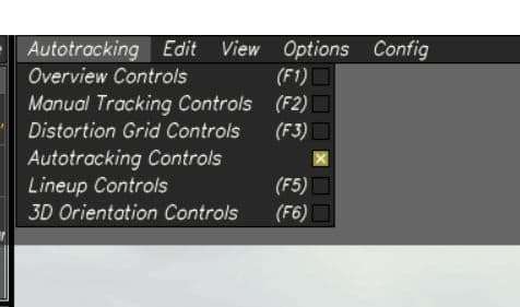
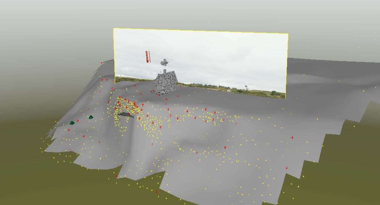
I wanted to have a 3D mesh of the environment before exporting the tracking into Maya, I made an automatic track to obtain hundreds of tracking points and create a mesh with them.
When tracking footage I always have in mind that the more manual tracking points I place the better the tracking will be.
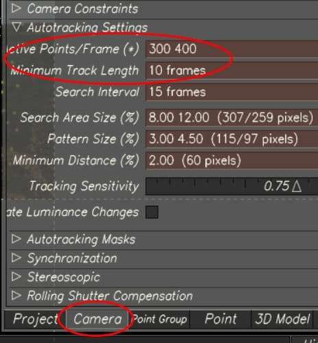
I changed to Autotracking controls and on the Camera settings changed the Active Points under the Autotracking Settings, I set the ‘Active Points/Frame’ to 300 400, meaning that it would place between 300 and 400 automatic points in an interval of 10 frames.
These points appeared in yellow, and because I was not going to use them to do any calculations, I selected all of them and set them to Passive.

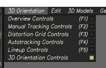
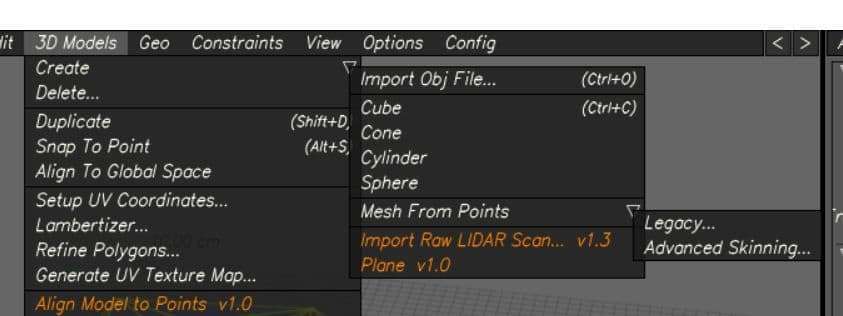
To create a mesh with the point cloud first I selected all the points I wanted to use to create the mesh. I changed to 3D Orientation Controls, and then clicked ‘3D models’ > ‘Create’ >’ Mesh From Points’ > select ‘Legacy’ or ‘Advanced Skinning’ (either one will create a 3D mesh).
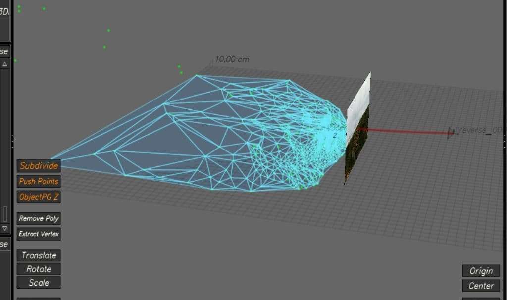
To make sure the mesh was exported with the tracking, I set ‘All 3D Models’ on the Export
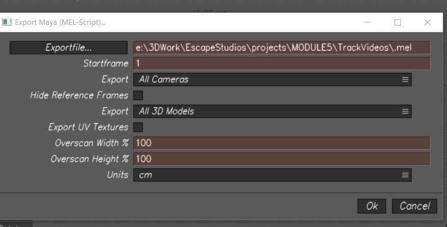
To model the house I used Autodesk Maya. I started blocking out the house following the floor plans and references from the movie to make sure the dimensions were accurate. Once I was pleased with how it was looking I started adding all the different details such as the wooden planks, the roof tiles, windows, etc.


The UV mapping required a lot of planning since the house had hundreds of pieces. I decided to separate the UV tiles by materials and by colours, this way I was able to texture easily as each tile had objects with the same materials and colours.

To have a clear view of what I had UV mapped and in which tile, I labelled them in a separate document.

I used Substance Painter for texturing. Because I was close to the deadline for finishing the textures I needed to work fast and smart. 90% of the materials were wood therefore I decided to start by texturing one UV tile that contained only wooden planks.
I used the ‘Wood Ship Hull Old’ Smart Material since it already contained all the different layers I needed and could save me a lot of time. I then hid all the layers and started editing them one by one to what I needed them to look like by changing colours, adding more dirt, etc.
Once I was happy with the way the textures were looking I duplicated the material to be able to use it on the other UV tiles, as I had an overall look of the whole house I continued going back and forth making changes on the materials until I was satisfied with the results.

I made two different textures for the house, a dirty version and a clean one. I did this to see how the house would look once imported into the tracked scene and to be able to compare versions and select the one which would work best with the environment.
As I liked different aspects from both of them I decided to mix them, having some parts cleaner than others to create a final outcome.


To create the simulation of the balloons I used Houdini. I started by doing research to find if people had done it before. I watched several videos where the person would scatter the balloons onto a grid and would animate the balloons together to one point and therefore I decided to do this.

While searching for ideas on how to create the simulation I found Thibaut Van Waeyenbergh’s ArtStation page “Balloons! | Houdini Vellum Study” where he had re-created the balloon simulation from the movie. He posted his process tree on how to simulate the balloons, which I used as a reference. To recreate the simulation the process went as follow:
1. Create the canopy shape
2. Create the wire geometry
3. Create the balloon geometry
4. Connect the balloon and wire geometry
5. Simulate the geometry using forces (e.g. wind)
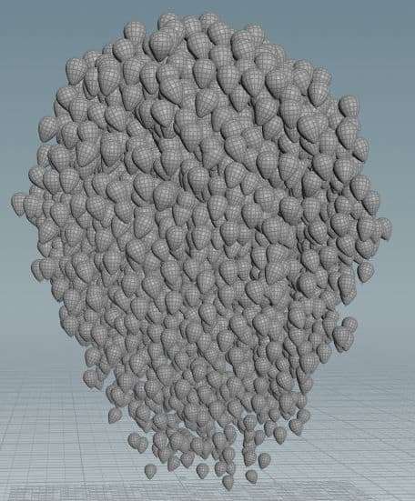
In the movie, the balloon simulation contained 10,297 balloons for shots of the house while flying; 20,622 for the lift off sequence and a varying number in other scenes. The movie did not only simulate the canopy but also the balloons inside of it. Initially I did that with 3500 balloons, but I did not get the shape I wanted, it looked more like an ellipse rather than a hot air balloon.
The solution to achieve the hot air balloon shape was to add more balloons, but the simulation time for 3500 balloons was already taking half a day and adding more balloons would increase the simulation time significantly. To be able to achieve this I was advised by my supervisor to simulate the canopy of the balloons and create a static geometry of balloons that would represent the balloons inside the canopy. So, instead of using 10,297 balloons, I used 2,500 in total.
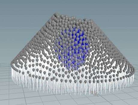
To create the static geometry I scattered points inside the canopy object I modelled, each of these points represented the position where each balloon would be placed and to randomise their scale I used an attribute randomize node.
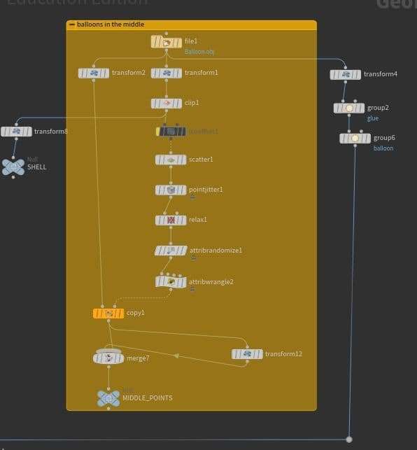
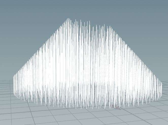
To create the wires, I created a circle shape grid and scattered points onto it, which represented the position of the wires. I then copied the wire geometry, which is essentially a line, onto the points. To have the balloons at the end of the wire I created a group node that would contain the beginning points of the wires.

To connect the balloons to the wire in the simulation, I had to make two groups called glue, one group that contained the beginning points of the wires and another group that contained the bottom of the balloons.
For the wires to stick to the grid I had to make a group that contains the end point of the wires. Later, I explain how I refer to those groups to simulate the balloons and wires correctly. The wires have different lengths based on where they are positioned, the closer the wire is to the center of the circle the longer the wire is. I decided to do this so the balloons would surround the static geometry properly.
After the geometry was created, I started creating the simulation.
I added a vellum cloth node at the end of the balloons geometry tree and a vellum hair node at the end of the wire geometry tree. In those nodes I modified parameters such as the thickness, the stiffness, the mass and the rest length to achieve the balloon simulation. In the vellum hair node there is an option to pin points to animation, there is where I refer to the pin group I mentioned earlier.
I then added two merge nodes where the first merge node combines the vellum geometry and the second merge node combines the constraint geometry. Those two merge nodes are then connected to the vellum solver node which is responsible for the simulation.
Because the balloons that are representing the canopy are interacting with the static balloons, which are inside the canopy, I connected the static geometry to the third input in the solver node, which is responsible for the collisions. In the solver node, I added a vellum constraint of the type glue, this was to make the balloons stick to the wires and not float off the wires when simulating.

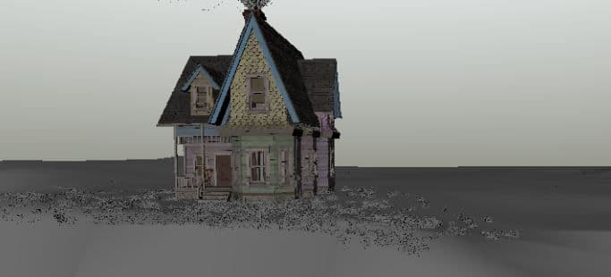
In the movie the balloons come out of the chimney. At this stage my balloons were scattered around on a grid and so in order to make it appear they were coming out of the chimney I had to animate the scattered points to one point or small area by scaling the grid from a high to a small value.
Once the balloons were simulated into one small area, I had to apply wind to the balloons. I decided to add wind to the simulation because the house was shot from a cliff and the shot would look more realistic if the balloons were interacting with the wind. I wanted the wind to blow from left to right to make the simulation realistic, and therefore I applied a VEX expression containing a sine function to the x-parameter of the wind force.
To make the shot look more interesting and realistic I decided to add low floating balloons. Therefore I made a second simulation, with only dozens of balloons. The simulation process was initially the same but I had to modify the rest length, gravity and stiffness of the wires much more to achieve the simulation of the low floating balloons. Once the simulation was done and imported into Maya, I proceeded to delete the balloons that were not complimenting the main simulation, leaving only the ones that did.
The lighting of the scene was straightforward as the footage was shot during an overcast day. Because I didn’t have an HDRI image of the environment, I used a skydome light and applied a ramp to it, matching the colours of the environment, this way the house and balloons would accurately reflect the colours of their surroundings. I also used a directional light to imitate the sun. Because the sun was hidden behind the clouds, the intensity on the light was set to a low value.
The simulation of the balloons had roughly 2500 balloons, and texturing one by one would have been very labour intensive. I searched for several ways to shade all of them at once and found a tutorial in the Arnold forum where it explained how to easily achieve this by using a 'utility' and 'color jitter' nodes, the balloons looked very realistic with the right amount of roughness and subsurface scattering creating a tight rubber-like look, in addition to this I was able to change the colours of the balloons very easily by testing with different gammas, hues and saturations in the 'color jitter' node.

To make the house look integrated into the scene I used a straw paintable mesh to put on the ground around the house, I placed this mesh covering the top of the cliff and applied a 'Shadow matte' material to it making the whole scene look more integrated as the mesh was casting shadows on the ground.

To set up the render I did two separate steps, the first one was to create the render layers and the second to set up the render settings such as the resolution, samples and AOVs.
I set up 3 render layers, one for the house and balloons, another for the ground and a last one for the grass.
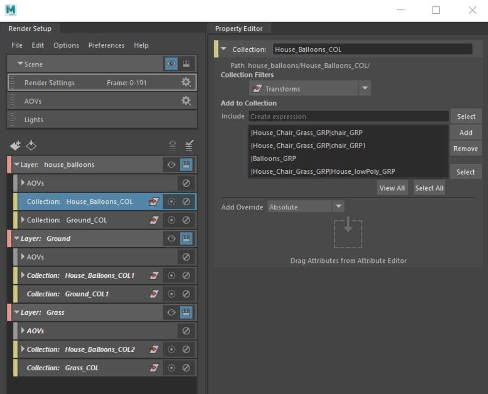
I proceeded to set up the render settings, as shown in the image below. I set the AA samples to 6 and the rest of them to 2 knowing that having the AA samples that high would increase the render time significantly, but it would also improve the quality of the images - which was needed. For the AOVs I used Diffuse (direct and indirect), specular (direct and indirect), emission, ambient occlusion, shadow matte, SSS, transmission and ID pass.

I used Nuke for the compositing of the final outcome. I imported the three image sequences of the layers I rendered and started breaking all the AOVs down, to then merge them together obtaining the final outcome.
The main layer that contained the house and the balloons required more work as it was the one containing all the AOVs mentioned before, doing this would facilitate making changes to each of them individually if I needed to. As I broke all of them down I started merging them together using ‘merge’ nodes.

To be able to properly integrate the scene into the back-plate I used ’Hue Shift’, ’Grade’, ’Grain’ and ’Color Correct’ nodes. Using the ’Grain’ node I was able to add noise to the house to match the noise of the original footage, and the ’Grade’, ’Color Correct’ and ’Hue Shift’ nodes, helped in adjusting the pigment of the house and balloons making it possible for me to ensure the overall look of the 3D objects matched the ambient colour of the footage.
To finish I want to give credits to Erica Melino, a compositing artist who helped me with the clean-up of the original footage.
You can find more of Camila's work on The Rookies, ArtStation and her Website.